This thread has been locked.
If you have a related question, please click the "Ask a related question" button in the top right corner. The newly created question will be automatically linked to this question.
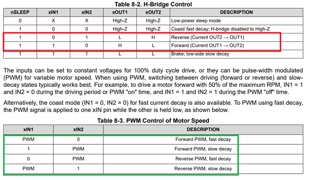
This signal was captured from the OUT1-4 pins of the DRV8411 However, once it was sent to the motor, it didnt rotate at all.
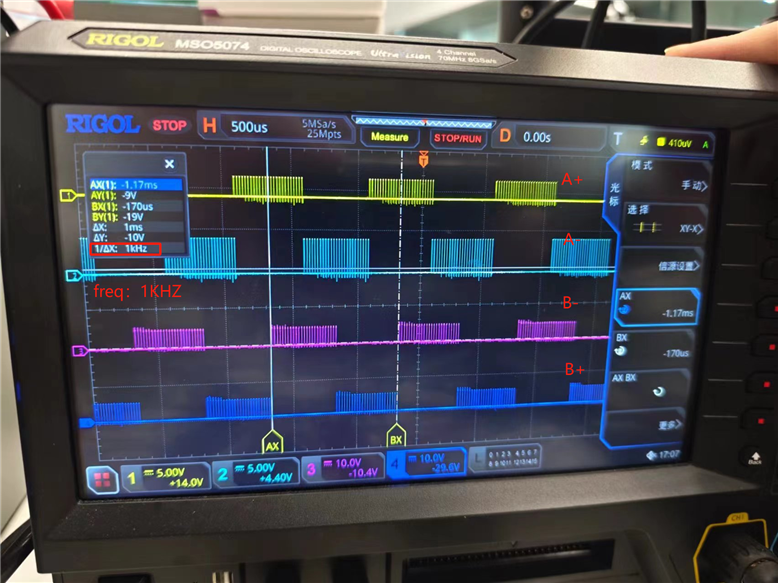
This is the waveform for each pulse,Is this signal all right?
There’s another issue: when the pulses are emitted, the chip’s power consumption is extremely low Not even 1mA of current
Could someone help answer these questions? Thank you very much!
plzzz
您好,
请参考数据手册“8.2 Functional Block Diagram”连接有刷直流电机。
电机驱动时的控制逻辑如下,OUT脚的输出波形请参考“Figure 8-2. H-Bridge Timing Diagram”
DRV8411 Dual H-Bridge Motor Driver with Current Regulation datasheet (Rev. C)
请根据评估板的设计文件检查电路设计。