This thread has been locked.

If you have a related question, please click the "Ask a related question" button in the top right corner. The newly created question will be automatically linked to this question.

AM62A7: 处理器论坛

Part Number: AM62A7

Hi 

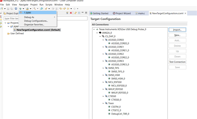
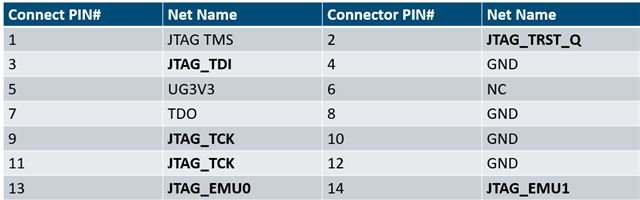
我们给SOC AM62A74的JTAG 连接如下

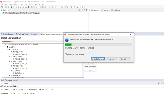
我们在用CCS连接JTAG时,点击Test connection时,显示连接已经成功;

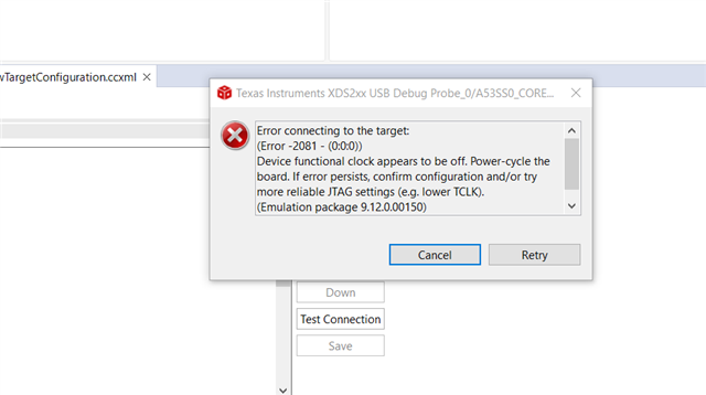
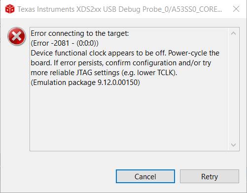
但尝试用JTAG去debug时,则会显示下面提示:

请问这大概是什么问题?

我们的板子是自己开发的,SOC内部现在是没有任何程序的。 时钟在硬件配置上正常,电源供电已经完成。

谢谢!

  • 另外,JTAG_TRST_Q我们目前是直接连接的SOC的F15脚 TRSTN. 

  • 请看一下是否有按照下面的电路图连接?
    Target Connection Design
    https://dev.ti.com/tirex/explore/node?node=AOi9Jj0vmBMJ0KQKaKITgg__FUz-xrs__LATEST

  • Hi Shine, 

    谢谢回复,对比下来对于14PIN连接方式,我们没有用到POR,但里面也提到这块并不是强制的。

    看上去似乎没有什么问题。还是对于我们XDS200系列仿真器,有特定要求?看里面只列举出了一个20PIN连接器的方式 给XDS200仿真器。

  • Hi Shine 

    I would like to post the step below. Hope you can help on this. 

    Firstly, I test the connection.

    Get the log below, I think it's saying that the connection is successful

    -------------

    [Start: Texas Instruments XDS2xx USB Debug Probe_0]

    Execute the command:

    %ccs_base%/common/uscif/dbgjtag -f %boarddatafile% -rv -o -S integrity

    [Result]


    -----[Print the board config pathname(s)]------------------------------------

    C:\Users\hhamming\AppData\Local\TEXASI~1\
    CCS\ccs1240\0\0\BrdDat\testBoard.dat

    -----[Print the reset-command software log-file]-----------------------------

    This utility has selected a 560/2xx-class product.
    This utility will load the program 'xds2xxu.out'.
    The library build date was 'Jun 2 2023'.
    The library build time was '17:37:16'.
    The library package version is '9.12.0.00150'.
    The library component version is '35.35.0.0'.
    The controller does not use a programmable FPGA.
    The controller has a version number of '13' (0x0000000d).
    The controller has an insertion length of '0' (0x00000000).
    This utility will attempt to reset the controller.
    This utility has successfully reset the controller.

    -----[Print the reset-command hardware log-file]-----------------------------

    This emulator does not create a reset log-file.

    -----[Perform the Integrity scan-test on the JTAG IR]------------------------

    This test will use blocks of 64 32-bit words.
    This test will be applied just once.

    Do a test using 0xFFFFFFFF.
    Scan tests: 1, skipped: 0, failed: 0
    Do a test using 0x00000000.
    Scan tests: 2, skipped: 0, failed: 0
    Do a test using 0xFE03E0E2.
    Scan tests: 3, skipped: 0, failed: 0
    Do a test using 0x01FC1F1D.
    Scan tests: 4, skipped: 0, failed: 0
    Do a test using 0x5533CCAA.
    Scan tests: 5, skipped: 0, failed: 0
    Do a test using 0xAACC3355.
    Scan tests: 6, skipped: 0, failed: 0
    All of the values were scanned correctly.

    The JTAG IR Integrity scan-test has succeeded.

    -----[Perform the Integrity scan-test on the JTAG DR]------------------------

    This test will use blocks of 64 32-bit words.
    This test will be applied just once.

    Do a test using 0xFFFFFFFF.
    Scan tests: 1, skipped: 0, failed: 0
    Do a test using 0x00000000.
    Scan tests: 2, skipped: 0, failed: 0
    Do a test using 0xFE03E0E2.
    Scan tests: 3, skipped: 0, failed: 0
    Do a test using 0x01FC1F1D.
    Scan tests: 4, skipped: 0, failed: 0
    Do a test using 0x5533CCAA.
    Scan tests: 5, skipped: 0, failed: 0
    Do a test using 0xAACC3355.
    Scan tests: 6, skipped: 0, failed: 0
    All of the values were scanned correctly.

    The JTAG DR Integrity scan-test has succeeded.

    [End: Texas Instruments XDS2xx USB Debug Probe_0]

    ------------------------

    I close it. And run debug like below:

    1. 

    2. The process will run like below:

    3. Then I'll be indicated with below picture:

    Could you know what has happened basing on these information ?

    Thank you,

  • 请尝试 下面的帖子里的方法,问题类似。

    The inability to connect to the cores may result from not initializing the board. Have you made sure the board is properly initialized may be with SBL NULL bootloader from AM62A MCU+ SDK

    https://software-dl.ti.com/mcu-plus-sdk/esd/AM62AX/09_00_00_19/exports/docs/api_guide_am62ax/EXAMPLES_DRIVERS_SBL_NULL.html


    https://e2e.ti.com/support/processors-group/processors/f/processors-forum/1280042/sk-am62a-lp-jtag-connection-to-am62a7-on-sk-am62a-lp-eval-board-failed/4860681

  • Hi Shine,

    It looks the initial configuration should be done before the debug by JTAG. 

    Other information is that we are debugging in our own AM62A74 board. Currently the CCS can't let the UART port work for we can't measure the output in the UART TX when we run the configuration file in CCS. 

    Do you have any user guide that can guide us to configure the TI tool step by step? In our AM62Ax board, we have used different OSPI Flash, LPDDR4 comparing with TI EVM board. 

    Thank you,

  • Currently the CCS can't let the UART port work for we can't measure the output in the UART TX when we run the configuration file in CCS. 

    那要检查一下uart串口的硬件电路了。先通过uart口烧写SBL NULL bootloader ,再连接JTAG。

  • Hi Shine,

    这个问题现在看应该还没到板子的硬件,诊断的结果是从PC端都没有输出任何信息。所以我在寻问是否有根据我们自己的板子一步步配置这个文件 的指导文件,里面包括软件配置和硬件配置。

  • PC端的COM口已经用串口调试工具验证过,是可以向外输出信息的。

  • 这个问题现在看应该还没到板子的硬件

    不是和板子的JTAG口连接时报错吗?

  • Hi Shine,

    现在JTAG报错后,我们用UART向SOC中Boot文件,但没有完合Boot成功。这块的流程一直不太清楚。

  • 请配置成uart boot mode,然后看有没有cccc打印出来,看板子的串口是否通的。

    • POWER-OFF the EVM
    • Set boot mode to UART BOOTMODE as shown in below image
    • POWER-ON the EVM
    • You should see character "C" getting printed on the UART terminal every 2-3 seconds as shown below