If you have a related question, please click the "Ask a related question" button in the top right corner. The newly created question will be automatically linked to this question.
Assembled Board with an external supply current limited, turn on the DC input power; Check DC in to 3.3v
measure DCtoDC converter 3.3v out, value, ripple/noise. Record DC into 3.3v ISK board
T3-2
Assembled Board, DC In applied, release PMIC NRST high, EN1 high, while keeping IWR6843 NRST low; Check DC out of PMIC 1.24v, 1.8v, 1.0v (if LDO used), 3.3v are within 2.5% of set point, use oscilloscope measure ripple, noise
measure PMIC output set point, ripple and noise; record DC current input as reset IWR current
T3-6
Power up the IWR device in SOP mode 2 measure the VBAP voltage on B10 ball
Make sure the VBGAP voltage is ~0.9V
T3-7
measure the clock frequency on the CLKP pin, also CLKM if connected to crystal
The frequency should be 40Mhz
T3-8
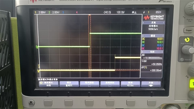
measure the WARM_RESET output, should be 6-8ms logic 1-> 0 at nRESET 0->1, Also check nERROR out = '1'
see power sequence, should be 1->0->1
T3-9
Measure the voltages on the "1p4V_APLL" and 1p4V_SYNTH" pins.
The voltages on both the pins should be ~1.4V
T3-10
Using Radar Studio configure the device with the desired chirp and frame configuration; Start the chirping with infinite number of frames ; Measure the voltage on the "VOUT_PA" pin


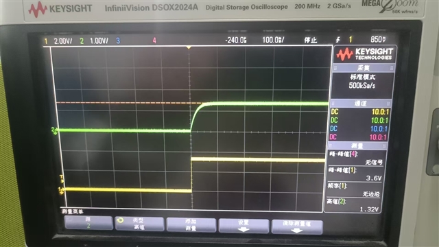 你看,我的复位高电平,只有1.32V。nRST的复位无效电平是1.57V,是不是我的复位上拉太弱,导致复位信号高电平达不到3.0V?