//发送数据

void Send_Byte(u8 cmd, u8 dat)
{
    /* Common I2C transaction setup */
       i2cTransaction.writeBuf   = txBuffer;
       i2cTransaction.writeCount = 2;
       i2cTransaction.readBuf    = rxBuffer;
       i2cTransaction.readCount  = 0;

       i2cTransaction.slaveAddress = OLED_SLAVEADDR;
       txBuffer[0] = cmd;
       txBuffer[1] = dat;
       if (!I2C_transfer(I2Chandle, &i2cTransaction)) {
           Log_error0("I2C Transaction fail!");
       }
}

void OLED_WR_Byte(u8 dat,u8 mode)
{

    if(mode != OLED_CMD)
    {
       Send_Byte(0x40, dat);
    }else
    {
        Send_Byte(0x00, dat);
    }


OLED 初始化:
    OLED_WR_Byte(0xAE,OLED_CMD);//--turn off oled panel
    OLED_WR_Byte(0xFD,OLED_CMD);
    OLED_WR_Byte(0x12,OLED_CMD);
    OLED_WR_Byte(0xd5,OLED_CMD);//--set display clock divide ratio/oscillator frequency
    OLED_WR_Byte(0xA0,OLED_CMD);
    OLED_WR_Byte(0xA8,OLED_CMD);//--set multiplex ratio(1 to 64)
    OLED_WR_Byte(0x3f,OLED_CMD);//--1/64 duty
    OLED_WR_Byte(0xD3,OLED_CMD);//-set display offset   Shift Mapping RAM Counter (0x00~0x3F)
    OLED_WR_Byte(0x00,OLED_CMD);//-not offset
    OLED_WR_Byte(0x40,OLED_CMD);//--set start line address  Set Mapping RAM Display Start Line (0x00~0x3F)
    OLED_WR_Byte(0xA1,OLED_CMD);//--Set SEG/Column Mapping     0xa0×óÓÒ·ŽÖÃ 0xa1Õý³£
    OLED_WR_Byte(0xC8,OLED_CMD);//Set COM/Row Scan Direction   0xc0ÉÏÏ·ŽÖà 0xc8Õý³£
    OLED_WR_Byte(0xDA,OLED_CMD);//--set com pins hardware configuration
    OLED_WR_Byte(0x12,OLED_CMD);
    OLED_WR_Byte(0x81,OLED_CMD);//--set contrast control register
    OLED_WR_Byte(0xBF,OLED_CMD);// Set SEG Output Current Brightness
    OLED_WR_Byte(0xD9,OLED_CMD);//--set pre-charge period
    OLED_WR_Byte(0x25,OLED_CMD);//Set Pre-Charge as 15 Clocks & Discharge as 1 Cloc
    OLED_WR_Byte(0xDB,OLED_CMD);//--set vcomh
    OLED_WR_Byte(0x34,OLED_CMD);//Set VCOM Deselect Level
    OLED_WR_Byte(0xA4,OLED_CMD);// Disable Entire Display On (0xa4/0xa5)
    OLED_WR_Byte(0xA6,OLED_CMD);// Disable Inverse Display On (0xa6/a7)
    OLED_Clear();
    OLED_WR_Byte(0xAF,OLED_CMD);
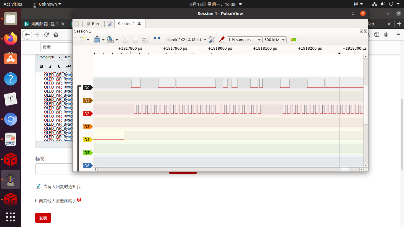
D0:SDA
D2:SCL
D4: RES