This thread has been locked.
If you have a related question, please click the "Ask a related question" button in the top right corner. The newly created question will be automatically linked to this question.
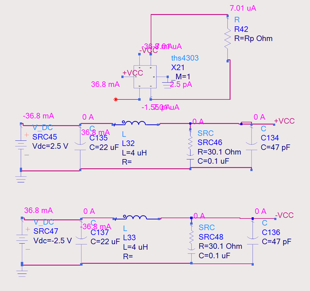
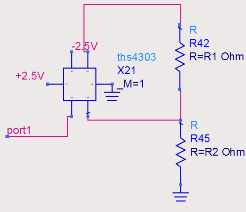
I downloaded the THS4303spice model, and connected the components in ADS to simulate the schematic diagram.
However, the voltage and current cannot match the simulation results during the actual machining test.
For example, the simulated output voltage is 121mV, but the output voltage will become -0.71V during testing.
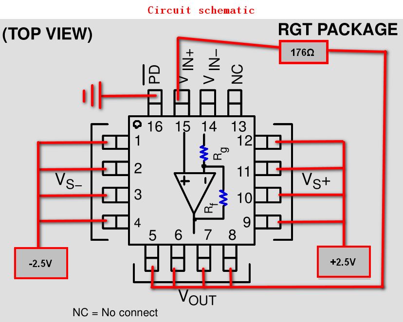
I follow the power supply method recommended in the manual to power the op amp.
I don’t know where the problem is, or the model itself is not accurate enough.
Thank you for help!
The schematic diagram in ADS is shown in the figure below,
the simulate voltage of the pin--------- vout, +vin and -vin all are 1.56V.
but the test voltage was different------- vout/-vin: -1.72V, +vin: when I first tested, it was -1.72V, but after connecting the voltmeter for a while, it becomes -0.03V.
Moreover, the test current of the positive and negative power supply ports of the op amp is also different from the simulation.
The simulation current is 36.8mA, but the test voltage is 18mA.
I just simulate the DC of the circuit, so there is no input voltage.
Thank you for your help!
This a non-foster circuit, it can produce a negtive impedance, After connecting the circuit, I want to check the DC of the circuit. But the simulation voltage of the +vin&-vin&vout was totally different from the actual measurement results. I don't know why this happens, it really caused by the negative pin hanging?