This thread has been locked.
If you have a related question, please click the "Ask a related question" button in the top right corner. The newly created question will be automatically linked to this question.
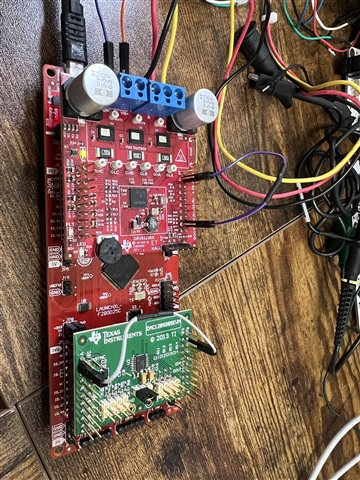
我正在将 TMS320F2.8379万D用于BLDC电机控制 应用。 我使用DRV832RX作为驱动器和功率级。 是否有任何与我的应用程序非常匹配的TI SDK示例代码?
RV832RX[/报价2000报价]108.9236万]</s>2.8379万 2.8379万似乎这个零件名称不正确。 没有使用DRV8323RS的TMS320F2.8379万D的示例。 您可以找到TMS320F28.0025万和 DRV8323RS的示例。
您可以 下载并安装最新的MotorControlSDK。 有一个新的通用电机控制实验室,其中包括您所需的基于F2.8002万x的BLDC电机控制。 有关本实验的详细介绍可通过以下链接在实验用户指南中找到。 您可以按照指南将实验室移植到 您使用的TMS320F2.8379万D。
C2000WARE-MOTORCONTROL-SDK:https://www.ti.com/tool/C2000WARE-MOTORCONTROL-SDK
通用项目和实验室用户指南:https://www.ti.com/lit/spruj26
以下文件夹中的示例实验室项目:C:\ti\c2000\C2000Ware_MotorControl_SDK_<version>\solutions\universal_motorcontrol_lab\f28002x</s>2000 2.8002万
您好Yanming,
根据 通用电机控制实验室用户指南,我正在使用DRV8323RS评估TMS320F28.0025万。 完成硬件设置后,根据用户指南,我正在进行1级构建,但 运行代码时,我的变量值与用户指南的描述不匹配(图2-25)。 马达电压被正确感应,但变量'DotorVars_M1.ISRC'没有增加 ,我无法通过将'OtorVars_M1.FlagEnableRunAndIdentify'设置为1来启动马达。
GPIO29 必须 连接 到LAUNCXL-F28.0025万C上的DRV8323启用引脚。 因此您需要将LAUNCHLL-F28.0025万C上的S2设置为(1:1)位置,GPIO28&GPIO29需要通过将S2的SEL1设置为1 (靠近USB仿真器)来路由到BP头。
或者,您可以查看下面有类似问题的链接。
我已将 LAUNCHTXL-F28.0025万C上的S2位置更改为 (1:1)。 之后,正如您在 本票证中提到 的,用户需要修改ISR计数的代码以增加。
"...以下代码已在发行代码中删除。 如果需要,可以将其添加到motor1_drive.c文件的motor1CtrlISR()中。
MotorVars_M1.ISRCount++;
"
我修改了此代码以增加ISR。 现在,计数器在递增,但电机仍不旋转。 用于观察数组[0] t的第一个元素的offset_V_SF与实验手册中的0.5 值相差很远。 此外,我注意到ePWM的表达式 与实验室建议的不同(1666与1250)。
谢谢!
Jagbir
1.不需要在制造级别1中连接电机,电机不会在此级别运行,
2.电压偏移值仍然不正确,请按照实验指南,通过运行内部版本1的实验来检查bootxl和launchxl之间的连接。
您好Yanming,
我尝试观察在外部示波器上构建的1级输出。 我正在探测DRV8323RS evalkit上J4的引脚(1,3**11),但我 无法 在这些引脚上看到任何PWM波形。 是否未生成PWM或我正在探测错误的针脚。
反馈:
实验指南中有大量的遗漏和更正。 到目前为止,使用此实验室文档的整个体验都非常令人沮丧。
感谢您的反馈。 实验室指南正在根据客户和FAE的反馈进行修订,并将很快更新。
我似乎只有在使用Launchxl-f28.0025万C的DRV8323RS中缺少的内容可能是 Launchxl-f28.0025万C上的交换机S2设置。
是的。 带有50 % 占空比的PWM信号应探测到引脚(1/3/4/5/6/11)。
请将直流电源(12V~40V)连接到 DRV8323RS 转换卡,并按照指南将 DRV8323RS安装到 Launchxl-f28.0025万C,请确保Booster -DRV8323RS嵌入 到Launchxl-f2800C的右侧(J1/J3和J2/J4,靠近USB连接器),方向正确。
在 BOOSTXL-DRV8323RS上:
在LAUNCXL-F28.0025万C上:
在实验室项目中:
您好Yanming,
感谢您的回复。 我能够将实验室运行到2级,然后旋转电机。 为什么 我观察到其中一个阵列元件的电流和电压偏移不同。 其中一个阶段的不同偏移会产生什么后果? 我是否需要删除此偏移量,然后才能转到3级和4级构建。
Jagbir,
希望让您知道,TI的明天是美国假期。 请在周一结束前收到我们的下一个回复。
最佳,
Matthew
如果为电压感应设置了正确的ADC通道,并且电容器已安装在增压器逆变器板上,请检查ADC配置。 偏移校准值应与实验中显示的值相似。
如果要使用快速算法运行实验室,这些偏移必须正确,否则,您无法使用4级运行电机。
您好,
我想使用不同的BLDC电机。 需要修改实验练习中的哪些文件才能使用不同的马达。
根据 电机数据表设置/更改"user_mtr1.h"中的右侧电机参数。 并非所有参数都是必需的,请按照实验室指南更改相关参数。
#define user_motor1_type motor_type_pm
#define user_motor1_NUM_pole_pairs (4)
#define user_motor1_rrr_Ohm (空)
#define user_motor1_Rs_Ohm (0.4.52883422亿f)
#define user_motor1_LS_d_H (0.0.0148万176361f)17.6361万)
#define user_motor1_LS_q_H (0.0.0148万176361f)17.6361万)
#define user_motor1_rate_fluone_vpHz (0.0401013345f)
#define user_motor1_magniting_current_A (空)
#define user_motor1_RES_EST_CURRENT_A (1.5f)
#define user_motor1_IND_EST_CURRENT_A (-1.0f)
#define user_motor1_MAX_current_A (6.0f)
#define user_motor1_flue_exc_FREQ_Hz (40.0f)
#define user_motor1_NUM_ENC_SLOTS (1000)
#define user_motor1_inerty_Kgm2 (7.0.6154万e-06)
#define user_motor1_FREQ_NEARZEROLIMIT_Hz (5.0f)// Hz
#define user_motor1_rated电压_V (24.0f)
#define user_motor1_rate_speed_Krpm (3.0F)
#define user_motor1_FREQ_min_Hz (9.0f)// Hz
#define user_motor1_FREQ_MAX_Hz (600.0f)// Hz
#define user_motor1_FREQ_low_Hz (5.0f)// Hz
#define user_motor1_FREQ_hate_Hz (300.0f)// Hz
#define user_motor1_vol_min_V (5.0f)//电压
#define user_motor1_vol_MAX_V (24.0f)//电压
#define user_motor1_force_delta (0.05f)// a
#define user_motor1_align_delta (0.01f)// a
#define user_motor1_flue_current_a (0.5f)// a
#define user_motor1_align_current_a (1.0f)// a
#define user_motor1_startup_current_A (3.0F)// A
#define user_motor1_Torque_Current_A (2.0f)// a
#define user_motor1_over当前_A (6.5f)// a
#define user_motor1_Brake当前_A (1.0f)// A
#define user_motor1_Brake时间延迟(1.2万U)// 60s/5ms
#define user_motor1_speed_start_Hz (30.0f)
#define user_motor1_speed_force_Hz (25.0f)
#define user_motor1_ACCEL_START_Hzps (10.0f)
#define user_motor1_ACCEL_MAX_Hzps (50.0f)
#define user_motor1_speed_fs_hz (3.0F)
//仅适用于编码器
#define user_motor1_ENC_POS_MAX (user_motor1_NUM_ENC_SLOTS * 4 - 1)
#define user_motor1_ENC_POS_OFFSET (668)
//仅适用于ESMO
#define user_motor1_KSLIDE_MAX (0.75f)//
#define user_motor1_KSLIDE_MIN (0.15f)
#define user_motor1_PLL_KP_MAX (6.75f)//
#define user_motor1_PLL_KP_min (0.75f)
#define user_motor1_PLL_KP_SF (5.0f)
#define user_motor1_BEMF_threshold (0.5f)
#define user_motor1_BEMF_KSLF_FC_Hz (1.0f)
#define user_motor1_THETA_OFFSET _SF (1.0f)
#define user_motor1_speed_lpf_fc_hz (200.0f)
//用于是- BLDC
#define user_motor1_ramd_start_Hz (3.0F)
#define user_motor1_ramd_end_Hz (30.0f)
#define user_motor1_ramd_delay (5)
#define user_motor1_ISBLDC_INT_MAX (0.015f)
#define user_motor1_ISBLDC_INT_MIN (0.010f)
//用于Rs在线校准
#define user_motor1_RSONLINE_WAY_TIME (6万U)// 5m5/300s (5毫秒基准)
#define user_motor1_RSONLINE_work _time (2.4万U)//2min/120s at 5ms base
您好Yanming,
我正在使用自己的电机运行构建级别2。 我已 根据电机数据表修改了"user_mtr1.h"。 我收到以下错误标志。 任何见解都将有所帮助。
谢谢。
您使用的是哪种控制算法? 如果要获得正确的反馈速度,您必须设置正确的电机参数。
如果motorVars_M1.faultMtrUse.all等于0,则无需注意motorVars_M1.faultMtrPrev中的设置值。
我认为我已正确输入我的电机参数。 我正在使用快速算法,根据实验室的2级构建,使用V/F,I/F控制。
如上所述,检查ADC是否正确配置了电流和电压感应的正确通道。 似乎未在项目中正确配置它。 电压偏移不正确,因此相位电压反馈信号不正确,无法估计电动机的速度和角度。
//############################################################################# // $TI Release: MotorControl SDK v4.00.00.00 $ // $Release Date: Thu Feb 17 18:05:20 CST 2022 $ // $Copyright: // Copyright (C) 2017-2019 Texas Instruments Incorporated - http://www.ti.com/ // // Redistribution and use in source and binary forms, with or without // modification, are permitted provided that the following conditions // are met: // // Redistributions of source code must retain the above copyright // notice, this list of conditions and the following disclaimer. // // Redistributions in binary form must reproduce the above copyright // notice, this list of conditions and the following disclaimer in the // documentation and/or other materials provided with the // distribution. // // Neither the name of Texas Instruments Incorporated nor the names of // its contributors may be used to endorse or promote products derived // from this software without specific prior written permission. // // THIS SOFTWARE IS PROVIDED BY THE COPYRIGHT HOLDERS AND CONTRIBUTORS // "AS IS" AND ANY EXPRESS OR IMPLIED WARRANTIES, INCLUDING, BUT NOT // LIMITED TO, THE IMPLIED WARRANTIES OF MERCHANTABILITY AND FITNESS FOR // A PARTICULAR PURPOSE ARE DISCLAIMED. IN NO EVENT SHALL THE COPYRIGHT // OWNER OR CONTRIBUTORS BE LIABLE FOR ANY DIRECT, INDIRECT, INCIDENTAL, // SPECIAL, EXEMPLARY, OR CONSEQUENTIAL DAMAGES (INCLUDING, BUT NOT // LIMITED TO, PROCUREMENT OF SUBSTITUTE GOODS OR SERVICES; LOSS OF USE, // DATA, OR PROFITS; OR BUSINESS INTERRUPTION) HOWEVER CAUSED AND ON ANY // THEORY OF LIABILITY, WHETHER IN CONTRACT, STRICT LIABILITY, OR TORT // (INCLUDING NEGLIGENCE OR OTHERWISE) ARISING IN ANY WAY OUT OF THE USE // OF THIS SOFTWARE, EVEN IF ADVISED OF THE POSSIBILITY OF SUCH DAMAGE. // $ //############################################################################# #define USER_MTR1_H // //! \file /solutions/universal_motorcontrol_lab/common/include/user_mtr1.h //! \brief Contains the user related definitions //! // //***************************************************************************** // // If building with a C++ compiler, make all of the definitions in this header // have a C binding. // //***************************************************************************** #ifdef __cplusplus extern "C" { #endif //***************************************************************************** // //! \defgroup USER USER //! @{ // //***************************************************************************** // // the includes // modules #include "userParams.h" #include "user_common.h" // ***************************************************************************** // the defines //------------------------------------------------------------------------------ //#define BSXL8323RS_REVA //! \brief Defines the nominal DC bus voltage, V //! #define USER_M1_NOMINAL_DC_BUS_VOLTAGE_V (48.0f) //! \brief Defines the maximum voltage at the AD converter #define USER_M1_ADC_FULL_SCALE_VOLTAGE_V (57.52845691f) //! \brief Defines the analog voltage filter pole location, Hz #define USER_M1_VOLTAGE_FILTER_POLE_Hz (680.4839141f) // 47nF //! \brief Defines the maximum current at the AD converter #define USER_M1_ADC_FULL_SCALE_CURRENT_A (47.14285714f) // gain=10 //! \brief ADC current offsets for dc-link // the dc-link offset current for BSXL8323RS_REVA #define USER_M1_IDC_OFFSET_A (USER_M1_ADC_FULL_SCALE_CURRENT_A / 2.0f) //! \brief ADC current offsets for A, B, and C phases #define USER_M1_IDC_OFFSET_AD (2048.0f) #define USER_M1_IDC_OFFSET_AD_MAX (USER_M1_IDC_OFFSET_AD + 100.0f) #define USER_M1_IDC_OFFSET_AD_MIN (USER_M1_IDC_OFFSET_AD - 100.0f) //! \brief ADC current offsets for A, B, and C phases #define USER_M1_IA_OFFSET_AD (2030.99646f) #define USER_M1_IB_OFFSET_AD (2016.76001f) #define USER_M1_IC_OFFSET_AD (2007.99329f) //! \brief ADC voltage offsets for A, B, and C phases #define USER_M1_VA_OFFSET_SF (0.498977453f) #define USER_M1_VB_OFFSET_SF (0.497419506f) #define USER_M1_VC_OFFSET_SF (0.500700474f) //! \brief DC bus over voltage threshold #define USER_M1_OVER_VOLTAGE_FAULT_V (54.5f) //! \brief DC bus over voltage threshold #define USER_M1_OVER_VOLTAGE_NORM_V (52.5f) //! \brief DC bus under voltage threshold #define USER_M1_UNDER_VOLTAGE_FAULT_V (8.0f) //! \brief DC bus under voltage threshold #define USER_M1_UNDER_VOLTAGE_NORM_V (10.0f) //! \brief motor lost phase current threshold #define USER_M1_LOST_PHASE_CURRENT_A (0.2f) //! \brief motor unbalance ratio percent threshold #define USER_M1_UNBALANCE_RATIO (0.2f) //! \brief motor over load power threshold #define USER_M1_OVER_LOAD_POWER_W (50.0f) //! \brief motor stall current threshold #define USER_M1_STALL_CURRENT_A (90.8f) //! \brief motor fault check current threshold #define USER_M1_FAULT_CHECK_CURRENT_A (0.4f) //! \brief motor failed maximum speed threshold #define USER_M1_FAIL_SPEED_MAX_HZ (1500.0f) //! \brief motor failed minimum speed threshold #define USER_M1_FAIL_SPEED_MIN_HZ (5.0f) //! \brief Defines the number of failed torque //! #define USER_M1_TORQUE_FAILED_SET (0.000001f) // end of BSXL8323RS_REVA //------------------------------------------------------------------------------ //! \brief ADC current offsets checking value for A, B, and C phases #define USER_M1_IA_OFFSET_AD_MAX (USER_M1_IA_OFFSET_AD + 150.0f) #define USER_M1_IB_OFFSET_AD_MAX (USER_M1_IB_OFFSET_AD + 150.0f) #define USER_M1_IC_OFFSET_AD_MAX (USER_M1_IC_OFFSET_AD + 150.0f) #define USER_M1_IA_OFFSET_AD_MIN (USER_M1_IA_OFFSET_AD - 150.0f) #define USER_M1_IB_OFFSET_AD_MIN (USER_M1_IB_OFFSET_AD - 150.0f) #define USER_M1_IC_OFFSET_AD_MIN (USER_M1_IC_OFFSET_AD - 150.0f) //! \brief ADC voltage offsets for A, B, and C phases #define USER_M1_VA_OFFSET_SF_MAX (USER_M1_VA_OFFSET_SF + 0.05f) #define USER_M1_VB_OFFSET_SF_MAX (USER_M1_VB_OFFSET_SF + 0.05f) #define USER_M1_VC_OFFSET_SF_MAX (USER_M1_VC_OFFSET_SF + 0.05f) #define USER_M1_VA_OFFSET_SF_MIN (USER_M1_VA_OFFSET_SF - 0.05f) #define USER_M1_VB_OFFSET_SF_MIN (USER_M1_VB_OFFSET_SF - 0.05f) #define USER_M1_VC_OFFSET_SF_MIN (USER_M1_VC_OFFSET_SF - 0.05f) //****************************************************************************** //------------------------------------------------------------------------------ //! \brief Vbus used to calculate the voltage offsets A, B, and C // =0.5*USER_M1_NOMINAL_DC_BUS_VOLTAGE_V #define USER_M1_VBUS_OFFSET_V (0.5*USER_M1_ADC_FULL_SCALE_VOLTAGE_V) //! \brief Defines the maximum negative current to be applied in Id reference //! #define USER_M1_MAX_NEGATIVE_ID_REF_CURRENT_A ((float32_t)(-2.0)) //! \brief Defines the number of pwm clock ticks per isr clock tick //! Note: Valid values are 1, 2 or 3 only #define USER_M1_NUM_PWM_TICKS_PER_ISR_TICK (1) //! \brief Defines the number of ISR clock ticks per current controller clock tick //! #define USER_M1_NUM_ISR_TICKS_PER_CURRENT_TICK (1) //! \brief Defines the number of ISR clock ticks per speed controller clock tick //! #define USER_M1_NUM_ISR_TICKS_PER_SPEED_TICK (10) //! \brief Defines the number of current sensors //! #define USER_M1_NUM_CURRENT_SENSORS (3) //! \brief Defines the number of voltage sensors //! #define USER_M1_NUM_VOLTAGE_SENSORS (3) //! \brief Defines the Pulse Width Modulation (PWM) frequency, kHz //! #define USER_M1_PWM_FREQ_kHz ((float32_t)(15.0f)) #define USER_M1_PWM_TBPRD_NUM (uint16_t)(USER_SYSTEM_FREQ_MHz * 1000.0f / USER_M1_PWM_FREQ_kHz / 2.0f) //! \brief Defines the Pulse Width Modulation (PWM) period, usec //! #define USER_M1_PWM_PERIOD_usec ((float32_t)1000.0/USER_M1_PWM_FREQ_kHz) //! \brief Defines the Interrupt Service Routine (ISR) frequency, Hz //! #define USER_M1_ISR_FREQ_Hz (USER_M1_PWM_FREQ_kHz * (float32_t)1000.0 / (float32_t)USER_M1_NUM_PWM_TICKS_PER_ISR_TICK) //! \brief Defines the SFRA sampling, Hz //! #define MOTOR1_SAMPLING_FREQ_HZ USER_M1_ISR_FREQ_Hz //! \brief Defines the Interrupt Service Routine (ISR) period, usec //! #define USER_M1_ISR_PERIOD_usec (USER_M1_PWM_PERIOD_usec * (float32_t)USER_M1_NUM_PWM_TICKS_PER_ISR_TICK) //! \brief Defines the direct voltage (Vd) scale factor //! #define USER_M1_VD_SF ((float32_t)(0.95f)) //! \brief Defines the voltage scale factor for the system //! #define USER_M1_VOLTAGE_SF (USER_M1_ADC_FULL_SCALE_VOLTAGE_V / 4096.0f) //! \brief Defines the current scale factor for the system //! #define USER_M1_CURRENT_SF (USER_M1_ADC_FULL_SCALE_CURRENT_A / 4096.0f) //! \brief Defines the current scale invert factor for the system //! #define USER_M1_CURRENT_INV_SF (4096.0f / USER_M1_ADC_FULL_SCALE_CURRENT_A) //! \brief Defines the analog voltage filter pole location, rad/s //! #define USER_M1_VOLTAGE_FILTER_POLE_rps (MATH_TWO_PI * USER_M1_VOLTAGE_FILTER_POLE_Hz) //! \brief Defines the maximum Vs magnitude in per units allowed //! \brief This value sets the maximum magnitude for the output of the Id and //! \brief Iq PI current controllers. The Id and Iq current controller outputs //! \brief are Vd and Vq. The relationship between Vs, Vd, and Vq is: //! \brief Vs = sqrt(Vd^2 + Vq^2). In this FOC controller, the Vd value is set //! \brief equal to USER_MAX_VS_MAG*USER_VD_MAG_FACTOR. //! \brief so the Vq value is set equal to sqrt(USER_MAX_VS_MAG^2 - Vd^2). //! //! \brief Set USER_MAX_VS_MAG = 0.5 for a pure sinewave with a peak at //! \brief SQRT(3)/2 = 86.6% duty cycle. No current reconstruction //! \brief is needed for this scenario. //! //! \brief Set USER_MAX_VS_MAG = 1/SQRT(3) = 0.5774 for a pure sinewave //! \brief with a peak at 100% duty cycle. Current reconstruction //! \brief will be needed for this scenario (Lab08). //! //! \brief Set USER_MAX_VS_MAG = 2/3 = 0.6666 to create a trapezoidal //! \brief voltage waveform. Current reconstruction will be needed //! \brief for this scenario (Lab08). //! //! \brief For space vector over-modulation, see lab08 for details on //! \brief system requirements that will allow the SVM generator to //! \brief go all the way to trapezoidal. //! //#define USER_M1_MAX_VS_MAG_PU (0.66) //#define USER_M1_MAX_VS_MAG_PU (0.65) #define USER_M1_MAX_VS_MAG_PU (0.576) //#define USER_M1_MAX_VS_MAG_PU (0.565) //#define USER_M1_MAX_VS_MAG_PU (0.5) //! \brief Defines the reference Vs magnitude in per units allowed //! \ Set the value equal from 0.5 to 0.95 of the maximum Vs magnitude #define USER_M1_VS_REF_MAG_PU (float32_t)(0.8) * USER_MAX_VS_MAG_PU) //! \brief Defines the R/L excitation frequency, Hz //! #define USER_M1_R_OVER_L_EXC_FREQ_Hz ((float32_t)(300.0)) //! \brief Defines the R/L Kp scale factor, pu //! \brief Kp used during R/L is USER_M1_R_OVER_L_KP_SF * USER_M1_NOMINAL_DC_BUS_VOLTAGE_V / USER_MOTOR1_MAX_CURRENT_A; //! #define USER_M1_R_OVER_L_KP_SF ((float32_t)(0.02)) //! \brief Defines maximum acceleration for the estimation speed profiles, Hz/sec //! #define USER_M1_MAX_ACCEL_Hzps ((float32_t)(2.0)) //! \brief Defines the controller execution period, usec //! #define USER_M1_CTRL_PERIOD_usec (USER_M1_ISR_PERIOD_usec) //! \brief Defines the controller execution period, sec //! #define USER_M1_CTRL_PERIOD_sec ((float32_t)USER_M1_CTRL_PERIOD_usec/(float32_t)1000000.0) //! \brief Defines the IdRated delta to use during estimation //! #define USER_M1_IDRATED_DELTA_A ((float32_t)(0.0001)) #if defined(_FULL_FAST_LIB) //! \brief Defines the forced angle frequency, Hz #define USER_M1_FORCE_ANGLE_FREQ_Hz ((float32_t)(1.0)) //! \brief Defines the forced angle acceleration, Hz #define USER_M1_FORCE_ANGLE_ACCEL_Hzps ((float32_t)(10.0)) #else // !_FULL_FAST_LIB //! \brief Defines the forced angle frequency, Hz #define USER_M1_FORCE_ANGLE_FREQ_Hz ((float32_t)(1.0)) #endif // !_FULL_FAST_LIB //! \brief Defines the near zero speed limit for electrical frequency estimation, Hz //! The flux integrator uses this limit to regulate flux integration #define USER_M1_FREQ_NEARZEROSPEEDLIMIT_Hz ((float_t)(0.0f)) //! \brief Defines the fraction of IdRated to use during inductance estimation //! #define USER_M1_IDRATED_FRACTION_FOR_L_IDENT ((float32_t)(0.5)) //! \brief Defines the fraction of SpeedMax to use during inductance estimation //! #define USER_M1_SPEEDMAX_FRACTION_FOR_L_IDENT ((float32_t)(1.0)) //! \brief Defines the Power Warp gain for computing Id reference //! \brief If motor parameters are known, set this gain to: //! \brief USER_M1_PW_GAIN = SQRT(1.0 + USER_MOTOR1_Rr_Ohm / USER_MOTOR1_Rs_Ohm) //! #define USER_M1_PW_GAIN ((float32_t)(1.0)) //! \brief Defines the pole location for the DC bus filter, rad/sec //! #define USER_M1_DCBUS_POLE_rps ((float32_t)(100.0)) //! \brief Defines the pole location for the voltage and current offset estimation, rad/s //! #define USER_M1_OFFSET_POLE_rps ((float32_t)(20.0)) //! \brief Defines the pole location for the speed control filter, rad/sec //! #define USER_M1_SPEED_POLE_rps ((float32_t)(100.0)) //! \brief Defines the pole location for the direction filter, rad/sec //! #define USER_M1_DIRECTION_POLE_rps (MATH_TWO_PI * (float32_t)(10.0)) //! \brief Defines the pole location for the second direction filter, rad/sec //! #define USER_M1_DIRECTION_POLE_2_rps (MATH_TWO_PI * (float32_t)(100.0)) //! \brief Defines the pole location for the flux estimation, rad/sec //! #define USER_M1_FLUX_POLE_rps ( (float32_t)(10.0)) //! \brief Defines the pole location for the R/L estimation, rad/sec //! #define USER_M1_R_OVER_L_POLE_rps (MATH_TWO_PI * (float32_t)(3.2)) //! \brief Defines the convergence factor for the estimator //! #define USER_M1_EST_KAPPAQ ((float32_t)(1.5f)) //! \brief Defines the scale factor for the flux estimation //! the default value is 1.0f, change the value between 0.1f and 1.25f //! //#define USER_M1_EST_FLUX_HF_SF ((float32_t)(0.120f)) #define USER_M1_EST_FLUX_HF_SF ((float32_t)(0.250f)) //#define USER_M1_EST_FLUX_HF_SF ((float32_t)(1.00f)) //! \brief Defines the scale factor for the frequency estimation //! the default value is 1.0f, change the value between 0.5f and 1.5f //! #define USER_M1_EST_FREQ_HF_SF ((float32_t)(1.00f)) //! \brief Defines the scale factor for the bemf estimation //! the default value is 1.0f, change the value between 0.50f and 1.25f //! #define USER_M1_EST_BEMF_HF_SF ((float32_t)(1.00f)) //------------------------------------------------------------------------------ //! brief Define the Kp gain for Field Weakening Control #define USER_M1_FWC_KP 0.0225 //! brief Define the Ki gain for Field Weakening Control #define USER_M1_FWC_KI 0.00225 //! brief Define the maximum current vector angle for Field Weakening Control #define USER_M1_FWC_MAX_ANGLE -10.0f // degree #define USER_M1_FWC_MAX_ANGLE_RAD USER_M1_FWC_MAX_ANGLE /180.0f * MATH_PI //! brief Define the minimum current vector angle for Field Weakening Control #define USER_M1_FWC_MIN_ANGLE 0.0f // degree #define USER_M1_FWC_MIN_ANGLE_RAD USER_M1_FWC_MIN_ANGLE /180.0f * MATH_PI //! \brief Defines the number of DC bus over/under voltage setting time //! timer base = 5ms #define USER_M1_VOLTAGE_FAULT_TIME_SET (500) //! \brief Defines the number of motor over load setting time //! timer base = 5ms, 1s #define USER_M1_OVER_LOAD_TIME_SET (200) //! \brief Defines the number of motor stall setting time //! timer base = 5ms, 1s #define USER_M1_STALL_TIME_SET (200) //! \brief Defines the number of phase unbalance setting time //! timer base = 5ms, 5s #define USER_M1_UNBALANCE_TIME_SET (1000) //! \brief Defines the number of lost phase setting time //! timer base = 5ms, 10s #define USER_M1_LOST_PHASE_TIME_SET (2000) //! \brief Defines the number of over speed setting time //! timer base = 5ms #define USER_M1_OVER_SPEED_TIME_SET (600) //! \brief Defines the number of startup failed setting time //! timer base = 5ms, 10s #define USER_M1_STARTUP_FAIL_TIME_SET (2000) //! \brief Defines the number of over load setting times //! #define USER_M1_OVER_CURRENT_TIMES_SET (10) //! \brief Defines the number of stop wait time //! timer base = 5ms, 10s #define USER_M1_STOP_WAIT_TIME_SET (2000) //! \brief Defines the number of restart wait time //! timer base = 5ms, 10s #define USER_M1_RESTART_WAIT_TIME_SET (2000) //! \brief Defines the number of restart time //! #define USER_M1_START_TIMES_SET (3) //! \brief Defines the alignment time //! #define USER_M1_ALIGN_TIMES_SET (2000) // ctrl period //! //! #define USER_M1_QEP_UNIT_TIMER_TICKS (uint32_t)(USER_SYSTEM_FREQ_MHz/(2.0f * USER_M1_ISR_FREQ_Hz) * 1000000.0f) //============================================================================== // Motor defines //#define USER_MOTOR1 Estun_EMJ_04APB22_A //*Tested, FAST/eSMO/ENC //#define USER_MOTOR1 Estun_EMJ_04APB22_B //#define USER_MOTOR1 Regal_Beloit_5SME39DL0756 //#define USER_MOTOR1 Anaheim_BLWS235D //*Tested, FAST/Hall //#define USER_MOTOR1 Anaheim_BLY341S_48V //#define USER_MOTOR1 Anaheim_BLY341S_Y24V //#define USER_MOTOR1 Anaheim_BLY341S_D24V //#define USER_MOTOR1 tekin_redline_4600KV //#define USER_MOTOR1 low_voltage_ceiling_fan // ACI Motor //#define USER_MOTOR1 Marathon_5K33GN2A //#define USER_MOTOR1 Marathon_56H17T2011A //#define USER_MOTOR1 Dayton_3N352C //#define USER_MOTOR1 EMSYNERGY_LVACI //#define USER_MOTOR1 Anaheim_BLY172S_24V //*Tested, FAST/HALL #define USER_MOTOR1 Drill_Motor //*Tested, FAST/eSMO/ENC/HALL //#define USER_MOTOR1 Nedic_EPSMS037_D12V //#define USER_MOTOR1 Drone_BLK2BLADE //*Tested //#define USER_MOTOR1 Drone_SF_Black //*Tested //#define USER_MOTOR1 my_pm_motor_1 //#define USER_MOTOR1 my_aci_motor_2 #if (USER_MOTOR1 == Drill_Motor) #define USER_MOTOR1_TYPE MOTOR_TYPE_PM #define USER_MOTOR1_NUM_POLE_PAIRS (1) #define USER_MOTOR1_Rr_Ohm (NULL) #define USER_MOTOR1_Rs_Ohm (0.528f) #define USER_MOTOR1_Ls_d_H (0.000188295482f) #define USER_MOTOR1_Ls_q_H (0.000188295482f) #define USER_MOTOR1_RATED_FLUX_VpHz (0.0396642499f) #define USER_MOTOR1_MAGNETIZING_CURRENT_A (NULL) #define USER_MOTOR1_RES_EST_CURRENT_A (2.5f) #define USER_MOTOR1_IND_EST_CURRENT_A (-1.5f) #define USER_MOTOR1_MAX_CURRENT_A (20.0f) // Max. continuous current #define USER_MOTOR1_FLUX_EXC_FREQ_Hz (60.0f) #define USER_MOTOR1_NUM_ENC_SLOTS (1000) #define USER_MOTOR1_INERTIA_Kgm2 (0.179e-06) //1.79 gcm2 #define USER_MOTOR1_FREQ_NEARZEROLIMIT_Hz (5.0f) // Hz #define USER_MOTOR1_RATED_VOLTAGE_V (48.0f) #define USER_MOTOR1_RATED_SPEED_KRPM (60.0f) #define USER_MOTOR1_FREQ_MIN_HZ (9.0f) // Hz #define USER_MOTOR1_FREQ_MAX_HZ (600.0f) // Hz #define USER_MOTOR1_FREQ_LOW_HZ (5.0f) // Hz #define USER_MOTOR1_FREQ_HIGH_HZ (400.0f) // Hz #define USER_MOTOR1_VOLT_MIN_V (1.0f) // Volt #define USER_MOTOR1_VOLT_MAX_V (.0f) // Volt #define USER_MOTOR1_FORCE_DELTA_A (0.05f) // A #define USER_MOTOR1_ALIGN_DELTA_A (0.01f) // A #define USER_MOTOR1_FLUX_CURRENT_A (0.5f) // A #define USER_MOTOR1_ALIGN_CURRENT_A (1.5f) // A #define USER_MOTOR1_STARTUP_CURRENT_A (3.5f) // A #define USER_MOTOR1_TORQUE_CURRENT_A (2.0f) // A #define USER_MOTOR1_OVER_CURRENT_A (20.0f) // A #define USER_MOTOR1_BRAKE_CURRENT_A (1.0f) // A #define USER_MOTOR1_BRAKE_TIME_DELAY (12000U) // 60s/5ms #define USER_MOTOR1_SPEED_START_Hz (30.0f) #define USER_MOTOR1_SPEED_FORCE_Hz (25.0f) #define USER_MOTOR1_ACCEL_START_Hzps (10.0f) #define USER_MOTOR1_ACCEL_MAX_Hzps (20.0f) #define USER_MOTOR1_SPEED_FS_Hz (3.0f) // only for encoder #define USER_MOTOR1_ENC_POS_MAX (USER_MOTOR1_NUM_ENC_SLOTS * 4 - 1) #define USER_MOTOR1_ENC_POS_OFFSET (668) // Only for eSMO #define USER_MOTOR1_KSLIDE_MAX (0.75f) // #define USER_MOTOR1_KSLIDE_MIN (0.15f) #define USER_MOTOR1_PLL_KP_MAX (6.75f) // #define USER_MOTOR1_PLL_KP_MIN (0.75f) #define USER_MOTOR1_PLL_KP_SF (5.0f) #define USER_MOTOR1_BEMF_THRESHOLD (0.5f) #define USER_MOTOR1_BEMF_KSLF_FC_Hz (1.0f) #define USER_MOTOR1_THETA_OFFSET_SF (1.0f) #define USER_MOTOR1_SPEED_LPF_FC_Hz (200.0f) // for IS-BLDC #define USER_MOTOR1_RAMP_START_Hz (3.0f) #define USER_MOTOR1_RAMP_END_Hz (30.0f) #define USER_MOTOR1_RAMP_DELAY (5) #define USER_MOTOR1_ISBLDC_INT_MAX (0.015f) #define USER_MOTOR1_ISBLDC_INT_MIN (0.010f) // for Rs online calibration #define USER_MOTOR1_RSONLINE_WAIT_TIME (60000U) // 5min/300s at 5ms base #define USER_MOTOR1_RSONLINE_WORK_TIME (24000U) //2min/120s at 5ms base //! \brief Defines the maximum current slope for Id trajectory //! #define USER_M1_MAX_CURRENT_DELTA_A (USER_MOTOR1_RES_EST_CURRENT_A / USER_M1_ISR_FREQ_Hz) //! \brief Defines the maximum current slope for Id trajectory during power warp mode //! #define USER_M1_MAX_CURRENT_DELTA_PW_A (0.3 * USER_MOTOR1_RES_EST_CURRENT_A / USER_M1_ISR_FREQ_Hz) #ifndef USER_MOTOR1 #error Motor type is not defined in user_mtr1.h #endif #ifndef USER_MOTOR1_TYPE #error The motor type is not defined in user_mtr1.h #endif #ifndef USER_MOTOR1_NUM_POLE_PAIRS #error Number of motor pole pairs is not defined in user_mtr1.h #endif #ifndef USER_MOTOR1_Rr_Ohm #error The rotor resistance is not defined in user_mtr1.h #endif #ifndef USER_MOTOR1_Rs_Ohm #error The stator resistance is not defined in user_mtr1.h #endif #ifndef USER_MOTOR1_Ls_d_H #error The direct stator inductance is not defined in user_mtr1.h #endif #ifndef USER_MOTOR1_Ls_q_H #error The quadrature stator inductance is not defined in user_mtr1.h #endif #ifndef USER_MOTOR1_RATED_FLUX_VpHz #error The rated flux of motor is not defined in user_mtr1.h #endif #ifndef USER_MOTOR1_MAGNETIZING_CURRENT_A #error The magnetizing current is not defined in user_mtr1.h #endif #ifndef USER_MOTOR1_RES_EST_CURRENT_A #error The resistance estimation current is not defined in user_mtr1.h #endif #ifndef USER_MOTOR1_IND_EST_CURRENT_A #error The inductance estimation current is not defined in user_mtr1.h #endif #ifndef USER_MOTOR1_MAX_CURRENT_A #error The maximum current is not defined in user_mtr1.h #endif #ifndef USER_MOTOR1_FLUX_EXC_FREQ_Hz #error The flux excitation frequency is not defined in user_mtr1.h #endif #if ((USER_M1_NUM_CURRENT_SENSORS < 2) || (USER_M1_NUM_CURRENT_SENSORS > 3)) #error The number of current sensors must be 2 or 3 #endif #if (USER_M1_NUM_VOLTAGE_SENSORS != 3) #error The number of voltage sensors must be 3 #endif // ************************************************************************** // the Defines #define USER_M1_POT_ADC_MIN (200U) #define USER_M1_POT_SPEED_SF USER_MOTOR1_FREQ_MAX_HZ / ((float32_t)(4096.0f - USER_M1_POT_ADC_MIN)) //! \brief Defines the minimum frequency for pot #define USER_M1_POT_SPEED_MIN_Hz (USER_MOTOR1_FREQ_MAX_HZ * 0.1f) //! \brief Defines the maximum frequency input #define USER_M1_POT_SPEED_MAX_Hz (USER_MOTOR1_FREQ_MAX_HZ * 0.5f) //! \brief Defines the pot signal wait delay time #define USER_M1_WAIT_TIME_SET (500U) // 0.5s/1ms //! \brief Defines the minimum frequency for pulse input #define USER_M1_SPEED_CAP_MIN_Hz (20.0f) //! \brief Defines the maximum frequency for pulse input #define USER_M1_SPEED_CAP_MAX_Hz (600.0f) //! \brief Defines the pulse capture wait delay time #define USER_M1_CAP_WAIT_TIME_SET (200U) // 0.2s/1ms //! \brief Defines the switch signal wait delay time #define USER_M1_SWITCH_WAIT_TIME_SET (50U) // 0.05s/1ms // ************************************************************************** // the typedefs // ************************************************************************** // the globals // ************************************************************************** // the functions //! \param[in] pUserParams The pointer to the user param structure extern void USER_setMotor1Params(USER_Params *pUserParams); //***************************************************************************** // // Close the Doxygen group. //! @} // //***************************************************************************** //***************************************************************************** // // Mark the end of the C bindings section for C++ compilers. // //***************************************************************************** #ifdef __cplusplus } #endif // extern "C" #endif // end of USER_MTR1_H definition
我没有修改代码的ADC部分或任何代码文件。 我修改过的唯一文件是 user_mtr1.h,它用于添加 与我的电机相关的参数(请参阅随附的代码片段)。 是ADC偏移,具体取决于连接到系统的电机。 我需要修改代码的哪一部分来纠正此ADC偏移。 我看到的一种方法是修改user_mtr1.h 这是您所指的。
似乎C11上的电容器 未 正确填充。 请确保 BOOSTXL-DRV8323RS的C9,C10和C11上装有47nF电容器。
我将检查C11连接。 将C9,C10和C11添加到DRV8323评估板的目的是什么,如何确定47nF值。
这些电容器 用于过滤非连续PWM信号以进行电压感应。 它必须具有正确电容的电压感应功能。
我已确保在多评估套件的C9,C10和C11上连接了47nF,但我仍在观察偏移,特别是电压偏移。 我可以忽略这一偏移量。 如果不是,则如何删除此偏移。
如果要使用FAST算法,则不需要。 对其它算法是。 请检查ADC配置和板连接,以确保电流和电压感应正确。
您好Yanming,
我需要 将实验室的参考代码移植到 F3877X R 1.3 控制卡。 用户指南的第3.3 节中提供了代码更改说明。 使用 F3877X R 1.3 控制卡时,还需要对硬件进行哪些更改。
谢谢
无需对其它设备进行其它更改。 类似的更改如实验室指南中所示,适用于任何硬件套件。 请参阅用于更改上述PWM,ADC和GPIO配置代码的硬件套件示意图。 很抱歉,很难在此论坛上提供每个套件和客户自己的主板的详细更改,我们更愿意提供一个一般指南来说明如何迁移/移植实验室。