This thread has been locked.
If you have a related question, please click the "Ask a related question" button in the top right corner. The newly created question will be automatically linked to this question.
工具与软件:
大家好!
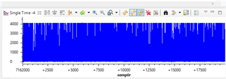
我正在从事一个辐射检测项目。 我需要在 C2000 Launchpad 中使用 ADC 对放大器电路(Cremat)的输出进行采样。 我确信代码和连接正常。 当我用示波器测量放大器的输出时、可以看到 γ 峰值、如下图所示。 然而、当我将放大器的输出连接到 C2000的 ADC 输入时、 我可以在图形上看到奇怪的数据。 如果我错过了阻抗匹配等方面的信息、您能给我提供帮助吗?
您好!
请参阅我们的 ADC 输入电路设计应用手册: https://www.ti.com/lit/spract6
我不认为该应用手册中包含的内容会导致您出现错误、因为这通常会导致您的输出低于预期。
您是否确定已正确设置图形? 如果你将 ADC 结果存储在一个缓冲器中、你是否看到大多数样本接近4096?
您是否使用了我们的示例? 如果是、哪一个?
此致、
Ben Collier
您好!
是的、我正在使用缓冲器、正如您所说的、大多数样本4095。 图形应该没问题。 代码附在下面。 我使用 TI 示例作为缓冲器、左侧是我的工作。
//########################################################################### // Author: Halit Durukan //########################################################################### #include "F28x_Project.h" // Device Headerfile and Examples Include File #define ADC_BUF_LEN 1000 //########################################################################### // Global variables used in the project before main function. Declare other // variables in this section of the code. //########################################################################### Uint16 Result = 0; Uint16 AdcBuf[ADC_BUF_LEN]; //########################################################################### // Declare the service routines and functions //########################################################################### interrupt void xint1_isr(void); interrupt void cpu_timer(void); interrupt void adcint1_isr(void); //###################### Beginning of the main code ####################### void main(void) { // Initialize System Control: // PLL, WatchDog, enable Peripheral Clocks // This example function is found in the F2837xD_SysCtrl.c file. InitSysCtrl(); // Clear all interrupts and initialize PIE vector table: // Disable CPU interrupts DINT; // Initialize the PIE control registers to their default state. // The default state is all PIE interrupts disabled and flags // are cleared. // This function is found in the F2837xD_PieCtrl.c file. InitPieCtrl(); // Disable CPU interrupts and clear all CPU interrupt flags: IER = 0x0000; IFR = 0x0000; // Initialize the PIE vector table with pointers to the shell Interrupt // Service Routines (ISR). // This will populate the entire table, even if the interrupt // is not used in this example. This is useful for debug purposes. // The shell ISR routines are found in F2837xD_DefaultIsr.c. // This function is found in F2837xD_PieVect.c. InitPieVectTable(); // Enable global Interrupts and higher priority real-time debug events: //EINT; // Enable Global interrupt INTM //ERTM; // Enable Global realtime interrupt DBGM //########################################################################### // User specific code: Your code comes here. //########################################################################### EALLOW; AdcaRegs.ADCCTL2.bit.PRESCALE = 6; //set ADCCLK divider to /4 AdcaRegs.ADCCTL1.bit.ADCPWDNZ = 1; //power up the ADC AdcaRegs.ADCCTL1.bit.INTPULSEPOS = 1; //Set interrupt pulse positions to late AdcaRegs.ADCCTL2.bit.RESOLUTION = 0; // 12-bit resolution AdcaRegs.ADCCTL2.bit.SIGNALMODE = 0; // Single-ended (12-bit mode only) DELAY_US(1000); //have to delay at least 500 microseconds before using ADC AdcaRegs.ADCSOC0CTL.bit.CHSEL = 0; //SOC0 will convert pin ADCINA0 AdcaRegs.ADCSOC0CTL.bit.ACQPS = 39; //0.2 micro seconds for sampling window (40 x 5ns = 0.2 micro secs) AdcaRegs.ADCSOC0CTL.bit.TRIGSEL = 0x01; //trigger on CPU Timer 0 CpuTimer0Regs.PRD.all = 10000 - 1;//Load period value. 20 kHz sampling (50 micro seconds period) CpuTimer0Regs.TPR.bit.TDDR = 0;//Set the prescale value for the timer as 1. CpuTimer0Regs.TCR.bit.TSS = 1;//Stop the timer. CpuTimer0Regs.TCR.bit.TRB = 1;//Reload the timer. CpuTimer0Regs.TCR.bit.TIE = 1;//Enable the Timer0 interrupt in the peripheral level. CpuTimer0Regs.TCR.bit.TSS = 0;//Start the timer. AdcaRegs.ADCINTSEL1N2.bit.INT1SEL = 0; //EOC0 will set INT1 flag AdcaRegs.ADCINTSEL1N2.bit.INT1CONT = 1; //interrupts will be generated //whether the ADCINTFLG is //cleared or not AdcaRegs.ADCINTSEL1N2.bit.INT1E = 1; //enable INT1 flag //Redirect the address of the ISR: PieVectTable.ADCA1_INT = &adcint1_isr; PieCtrlRegs.PIECTRL.bit.ENPIE = 1; // Enable the PIE block PieCtrlRegs.PIEIER1.bit.INTx1 = 1; // Enable PIE Group 1 INT1 ADCA1 IER |= M_INT1;//Enable CPU INT1 includes Xint1 EINT;//Enable global interrupt mask INTM. ERTM; EDIS; for (;;) { } } //###################### End of main code ####################### //#################### Interrupt Service Routines ################# interrupt void adcint1_isr(void) { static Uint16 *AdcBufPtr = AdcBuf; *AdcBufPtr++ = AdcaResultRegs.ADCRESULT0; // Brute Force the circular buffer if (AdcBufPtr == (AdcBuf + ADC_BUF_LEN)) { AdcBufPtr = AdcBuf; } //Result = AdcaResultRegs.ADCRESULT0; GpioDataRegs.GPBTOGGLE.bit.GPIO32 = 1; PieCtrlRegs.PIEACK.all = PIEACK_GROUP1; }
亲爱的本杰明:
我解决了我的问题,但想告诉你,我面临的问题,因为解决方案和问题本身非常有趣:D 我最后一次得到正确的结果是昨天。 从那时起、我就搜索了从产品说明书到论坛的每一个文档。 我正在更改采样窗口(ACQPS)和采样频率、但它根本不起作用。 在无数同样的琐碎之后,我开始觉得像一个白痴,因为它突然工作! 您能猜到发生了什么变化吗? 只是 PC 被拔下:D 出于某种原因,我需要在过去修理我的电脑,现在很清楚,几个电缆或螺钉出来:D 当我插入 PC 并使用 C2000时,它读周期性的噪音有某种原因。