If you have a related question, please click the "Ask a related question" button in the top right corner. The newly created question will be automatically linked to this question.
InitI2CGpio()
{
    EALLOW;

    //
    // Enable internal pull-up for the selected pins
    // Pull-ups can be enabled or disabled disabled by the user.
    // This will enable the pullups for the specified pins.
    // Comment out other unwanted lines.
    //
    GpioCtrlRegs.GPBPUD.bit.GPIO32 = 0;    // Enable pull-up for GPIO32 (SDAA)
    GpioCtrlRegs.GPBPUD.bit.GPIO33 = 0;	   // Enable pull-up for GPIO33 (SCLA)

    //
    // Set qualification for selected pins to asynch only
    // This will select asynch (no qualification) for the selected pins.
    // Comment out other unwanted lines.
    //
    GpioCtrlRegs.GPBQSEL1.bit.GPIO32 = 3;  // Asynch input GPIO32 (SDAA)
    GpioCtrlRegs.GPBQSEL1.bit.GPIO33 = 3;  // Asynch input GPIO33 (SCLA)

    //
    // Configure SCI pins using GPIO regs
    // This specifies which of the possible GPIO pins will be I2C functional
    // pins. Comment out other unwanted lines.
    //
    GpioCtrlRegs.GPBMUX1.bit.GPIO32 = 1;   // Configure GPIO32 to SDAA
    GpioCtrlRegs.GPBMUX1.bit.GPIO33 = 1;   // Configure GPIO33 to SCLA

    EDIS;
}
4. I2C初始化
void I2CA_Init(Uint16 iSlaveAddress,CommunicateSpeed_Enum eCommunicateSpeed)
{
    //IRS must be 0 while you configure/reconfigure the i2c module
    I2caRegs.I2CMDR.bit.IRS = 0;

    // Initialize I2C
    I2caRegs.I2CSAR = iSlaveAddress;		// Slave address

    // Configure I2C Module Clock
    #if (CPU_FRQ_150MHZ)             // Default - For 150MHz SYSCLKOUT
        I2caRegs.I2CPSC.all = 13;   // Prescaler - need 7-12 Mhz on module clk (150/15 = 10MHz)
    #endif
    #if (CPU_FRQ_100MHZ)             // For 100 MHz SYSCLKOUT
     I2caRegs.I2CPSC.all = 9;	    // Prescaler - need 7-12 Mhz on module clk (100/10 = 10MHz)
    #endif

    // Configure Communicate Speed
    if ( CommunicateSpeed_100K == eCommunicateSpeed )
    {
        I2caRegs.I2CCLKL = 60;          // NOTE: must be non zero
        I2caRegs.I2CCLKH = 30;           // NOTE: must be non zero
    }
    else if ( CommunicateSpeed_400K == eCommunicateSpeed )
    {
        I2caRegs.I2CCLKL = 10;          // NOTE: must be non zero
        I2caRegs.I2CCLKH = 5;           // NOTE: must be non zero
    }
    else
    {
        printf("Current I2C Communicate Speed Not Support");
    }

    // Configure Interrupt Source Enable
    I2caRegs.I2CIER.all = 0x00;		// Disable interrupts

    I2caRegs.I2CMDR.all = 0x0020;    // Take I2C out of reset
                                     // Stop I2C when suspended

    //I2caRegs.I2CMDR.bit.IRS = 1;	// Take I2C out of reset
    									// Stop I2C when suspended
    I2caRegs.I2CFFTX.all = 0x0000;	// Disable FIFO mode and TXFIFO
    I2caRegs.I2CFFRX.all = 0x0000;	// Disable RXFIFO, clear RXFFINT,

    return;
}
5. I2C写参数
Uint16 WriteData(Uint16 iSlaveAddress,Uint16 *pTxData,Uint16 iTxDataLen)
{
    Uint16 i;

    // Wait until the STP bit is cleared from any previous master communication.
    // Clearing of this bit by the module is delayed until after the SCD bit is
    // set. If this bit is not checked prior to initiating a new message, the
    // I2C could get confused.
    while(I2caRegs.I2CMDR.bit.STP == 1);

    // Check if bus busy
    while(I2caRegs.I2CSTR.bit.BB == 1);

    while(0 == I2caRegs.I2CSTR.bit.XRDY);

    I2caRegs.I2CSAR = iSlaveAddress;		// Slave address;
    I2caRegs.I2CCNT = iTxDataLen;
    I2caRegs.I2CDXR = pTxData[0];
    I2caRegs.I2CMDR.all = 0x6E20;

    for (i=0; i<iTxDataLen-1; i++)
    {
        printf("\r\n w1 here,I2CMDR:0x%04x,I2CSTR:0x%04x,I2CCNT:0x%04x,I2CDXR:0x%04x",I2caRegs.I2CMDR.all,I2caRegs.I2CSTR.all,I2caRegs.I2CCNT,I2caRegs.I2CDXR);
        while(0 == I2caRegs.I2CSTR.bit.XRDY);

        I2caRegs.I2CDXR = pTxData[i+1];
        if (I2caRegs.I2CSTR.bit.NACK == 1)
        {
            printf("\r\n w busy here1");
            return I2C_BUS_BUSY_ERROR;
        }
    }
    return I2C_SUCCESS;
}
6. I2C读函数
Uint16 ReadData(Uint16 iSlaveAddress,Uint16 *pTxData,Uint16 iTxDataLen,Uint16 *pRxData,Uint16 iRxDataLen)
{
    Uint16 i,Temp;

    // Wait until the STP bit is cleared from any previous master communication.
    // Clearing of this bit by the module is delayed until after the SCD bit is
    // set. If this bit is not checked prior to initiating a new message, the
    // I2C could get confused.
    while(I2caRegs.I2CMDR.bit.STP == 1);

    // Check if bus busy
    while(I2caRegs.I2CSTR.bit.BB == 1);

    I2caRegs.I2CSAR = iSlaveAddress;      // Slave address;;

    if ( (0 != iTxDataLen) && (NULL != pTxData) )	//判断是否需要在读取前先发送数据
    {
        while(0 == I2caRegs.I2CSTR.bit.XRDY);

        I2caRegs.I2CCNT = iTxDataLen;
        I2caRegs.I2CDXR = pTxData[0];
        I2caRegs.I2CMDR.all = 0x2620;
        if (I2caRegs.I2CSTR.bit.NACK == 1)
        {
            return I2C_BUS_BUSY_ERROR;
        }

        for (i=0; i<iTxDataLen-1; i++)
        {
            while(0 == I2caRegs.I2CSTR.bit.XRDY);

            I2caRegs.I2CDXR = pTxData[i+1];
            if (I2caRegs.I2CSTR.bit.NACK == 1)
            {
                return I2C_BUS_BUSY_ERROR;
            }
        }

        DELAY_US(50);
    }

    printf("\r\n r here1,I2CMDR:0x%04x,I2CSTR:0x%04x",I2caRegs.I2CMDR.all,I2caRegs.I2CSTR.all);
    while(0 == I2caRegs.I2CSTR.bit.XRDY);	//判断这个是否合适??
    // Wait Register-access-ready
    //while(I2caRegs.I2CSTR.bit.ARDY == 0);	//如果不需要先写入的读取,用这个判断也不合适??

    I2caRegs.I2CCNT = iRxDataLen;
    I2caRegs.I2CMDR.all = 0x2C20;
    if (I2caRegs.I2CSTR.bit.NACK == 1)
    {
        return I2C_BUS_BUSY_ERROR;
    }

    for(i=0; i<iRxDataLen; i++)
    {
        printf("\r\n r here2,I2CMDR:0x%04x,I2CSTR:0x%04x",I2caRegs.I2CMDR.all,I2caRegs.I2CSTR.all);
        while(0 == I2caRegs.I2CSTR.bit.RRDY);	//卡在这里

        Temp = I2caRegs.I2CDRR;
        if (I2caRegs.I2CSTR.bit.NACK == 1)
        {
            return I2C_BUS_BUSY_ERROR;
        }
        *pRxData = Temp;
        pRxData++;
    }
    return I2C_SUCCESS;
}
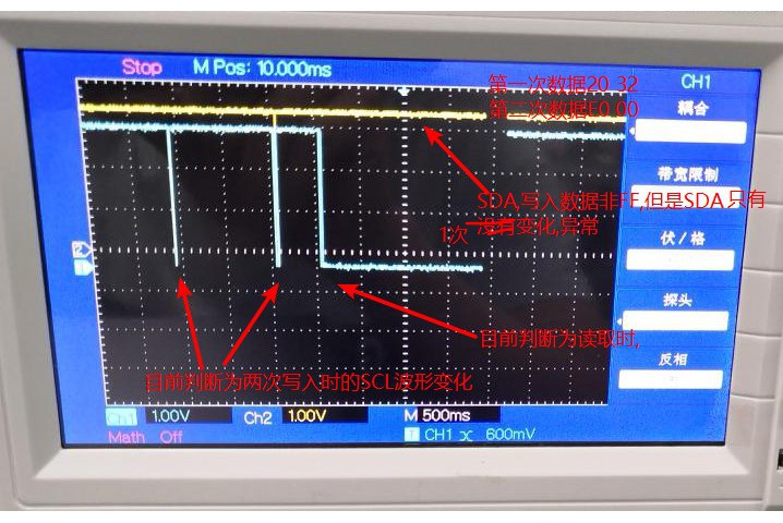
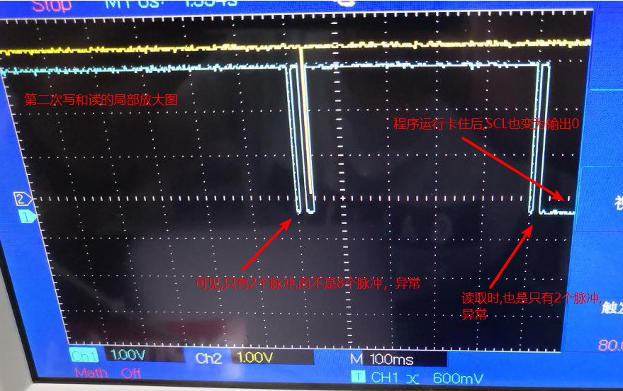
在while(0 == I2caRegs.I2CSTR.bit.RRDY);卡住,程序停止运行了。在其上一句调试信号为 r here2,I2CMDR:0x0c20,I2CSTR:0x3438