Part Number: TMS320F28335
您好,
我目前在使用 DSP (TMS320F28335) 與 FPGA板子 (PYNQ-Z2) 用 spi 通訊作溝通。
希望能夠以 DSP 作為 master 傳送浮點數數值 (例如: 0.12 0.121 0.122 ......) 到 作為 slave 的 FPGA ,但在測試時 FPGA 接收到的值有些會有錯誤。
原先猜測是會多一個0在最前面 (以2進制表示時),像是我原先要傳 1111111111111111 結果會變成 0111111111111111, 多的1會被推到下一列,試著手動全部往前推一位後仍然會一些值是錯的,
想知道這個問題是什麼導致的,以及該如何修正。
以下是往後移一位之後的部分結果 (紅色字為有嚴重錯誤):
0.120 -> 0.11951171606779099
0.121 -> 0.12099999934434891
0.122 -> 0.12200000137090683
0.123 -> 0.12300000339746475
0.124 -> 0.12399999797344208
0.125 -> 0.1259765774011612
0.126 -> 0.12502342462539673
0.127 -> 0.12797658145427704
0.128 -> 0.12702342867851257
0.129 -> 0.12997658550739288
0.130 -> 0.12902343273162842
......
另外,DSP這邊是以範例:
來做更改的,以下是我更改過的程式碼:
#include "DSP28x_Project.h" // Device Headerfile and Examples Include File
//#include "DSP2833x_Device.h"
//
// Function Prototypes
//
//__interrupt void ISRTimer2(void);
void delay_loop(void);
void spi_xmit(Uint16 a);
void spi_fifo_init(void);
void spi_init(void);
void error(void);
union datatype{
float f_type;
Uint16 u_type[2];
};
union datatype sdata;
union datatype rdata;
char data_switch=0;
//
// Main
//
void main(void)
{
sdata.f_type = 0.12;
//
// Step 1. Initialize System Control:
// PLL, WatchDog, enable Peripheral Clocks
// This example function is found in the DSP2833x_SysCtrl.c file.
//
InitSysCtrl();
//
// Step 2. Initialize GPIO:
// This example function is found in the DSP2833x_Gpio.c file and
// illustrates how to set the GPIO to it's default state.
//
// InitGpio(); // Skipped for this example
//
// Setup only the GP I/O only for SPI-A functionality
// This function is found in DSP2833x_Spi.c
//
InitSpiaGpio();
//
// Step 3. Clear all interrupts and initialize PIE vector table:
// Disable CPU interrupts
//
DINT;
//
// Initialize PIE control registers to their default state.
// The default state is all PIE interrupts disabled and flags
// are cleared.
// This function is found in the DSP2833x_PieCtrl.c file.
//
InitPieCtrl();
//
// Disable CPU interrupts and clear all CPU interrupt flags:
//
IER = 0x0000;
IFR = 0x0000;
//
// Initialize the PIE vector table with pointers to the shell Interrupt
// Service Routines (ISR).
// This will populate the entire table, even if the interrupt
// is not used in this example. This is useful for debug purposes.
// The shell ISR routines are found in DSP2833x_DefaultIsr.c.
// This function is found in DSP2833x_PieVect.c.
//
InitPieVectTable();
//
// Step 4. Initialize all the Device Peripherals:
// This function is found in DSP2833x_InitPeripherals.c
//
// InitPeripherals(); // Not required for this example
spi_fifo_init(); // Initialize the Spi FIFO
spi_init(); // init SPI
//
// Step 5. User specific code:
//
//
// Interrupts are not used in this example.
//
int count = 0;
for(;;)
{
if(count < 100)
{
spi_xmit(sdata.u_type[data_switch]);
while(SpiaRegs.SPIFFRX.bit.RXFFST !=1)
{
}
rdata.u_type[data_switch] = SpiaRegs.SPIRXBUF;
if(data_switch==0)
{
data_switch=1;
}
else
{
sdata.f_type = sdata.f_type + 0.001;
count ++;
data_switch=0;
}
delay_loop();
}
}
}
//
// delay_loop - Step 7. Insert all local Interrupt Service Routines (ISRs) and
// functions here:
//
void
delay_loop()
{
long i;
for (i = 0; i < 1000000; i++)
{
}
}
//
// error -
//
void
error(void)
{
__asm(" ESTOP0"); // Test failed!! Stop!
for (;;);
}
//
// spi_init -
//
void
spi_init()
{
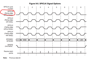
SpiaRegs.SPICCR.all =0x000F; // Reset on, rising edge, 16-bit char bits
//
// Enable master mode, normal phase, enable talk, and SPI int disabled.
//
SpiaRegs.SPICTL.all =0x0006;
SpiaRegs.SPIBRR =0x007F;
SpiaRegs.SPICCR.all =0x008F; // Relinquish SPI from Reset
SpiaRegs.SPIPRI.bit.FREE = 1; // Set so breakpoints don't disturb xmission
}
//
// spi_xmit -
//
void
spi_xmit(Uint16 a)
{
SpiaRegs.SPITXBUF=a;
}
//
// spi_fifo_init -
//
void
spi_fifo_init()
{
//
// Initialize SPI FIFO registers
//
SpiaRegs.SPIFFTX.all=0xE040;
SpiaRegs.SPIFFRX.all=0x204f;
SpiaRegs.SPIFFCT.all=0x0;
}
再麻煩替小弟我解惑了!!