TMS320F280039C: MCAN接收过滤器问题

Part Number: TMS320F280039C

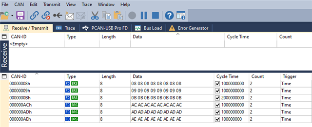
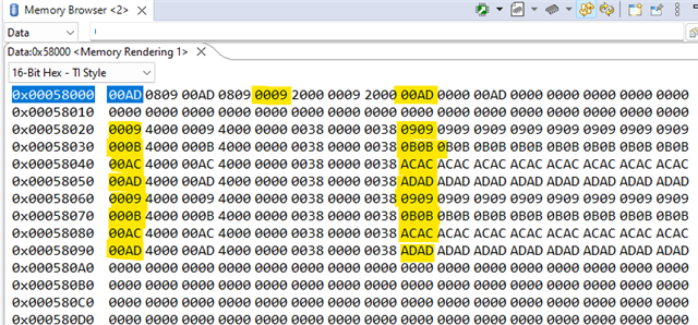
你好,我在配置280039C芯片的MCAN的过滤器时,发现第一个过滤器的sfid2无法正常工作,请问是什么原因呢?具体配置如下:

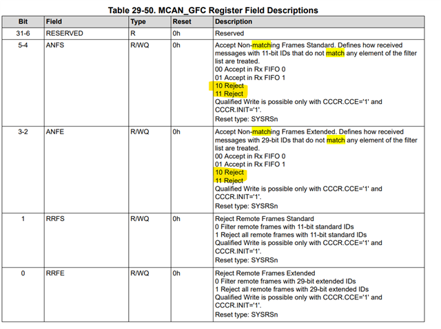
ConfigParams.filterConfig.anfs = 2U;

MCAN_config(MCANA_DRIVER_BASE, &ConfigParams );

StdFilterElement.sfid1 = 0x009U;

StdFilterElement.sfid2 = 0x0ADU;

StdFilterElement.sfec = 1U;

StdFilterElement.sft = 1U;

MCAN_addStdMsgIDFilter(MCANA_DRIVER_BASE, 0U,  &StdFilterElement);

配置如上,sfid1正常工作,但是sfid2无法工作,请问是什么原因呢

  • 感谢您对TI产品的关注!
    关于你的咨询,我们正在确认你的问题,稍后回复您。

  • SFID2确定Rx缓冲元素(在64个可能的元素中),其中将存储接受的帧(由相应的过滤器元素确定)。请参考C2000软件示例“mcan_ex10_receive_multiple_buffers”以了解其实现。

    mcan_ex10_receive_multiple_buffers

  • 在上述例程中,

    1.0x1属于过滤ID么?如果接收ID有0x1会怎么样?

    2.为什么StdFilterElement.sfec = 1U;这种模式的两个ID不可以用?
    3.例程没有配置filterConfig.anfs ,不是所有ID都会接受么?

  • ANFS=2表示不匹配的消息被拒绝。
    StdFilterElement.sfec=1U;-->匹配的消息存储在RX FIFO0中
    StdFilterElement.sft=1U;-->使用两个ID过滤器(从SFI1到SFID2)来过滤传入消息。
    因此,根据您的配置,ID为0x09到0xAD的消息将存储在FIFO0中。所有其他不匹配的消息都将被拒绝。

  • 请问这个filter ID存在内存的哪个位置呢?我想看一下是不是被覆盖了,在0x0000这个地址上没有发现存储的filter ID

  • 通常,过滤设置位于MCAN消息RAM的开头。但它也可以位于MCAN配置定义的其他位置。
    例如:

    msgRAMConfigParams.flssa = MCAN_STD_ID_FILT_START_ADDR;  // Standard ID Filter List Start Address.
    msgRAMConfigParams.lss = MCAN_STD_ID_FILTER_NUM;               // List Size: Standard ID.

    msgRAMConfigParams.flesa = MCAN_EXT_ID_FILT_START_ADDR; // Extended ID Filter List Start Address.
    msgRAMConfigParams.lse = MCAN_EXT_ID_FILTER_NUM;              // List Size: Standard ID.

  • 如你所说,我在上述地址没有发现配置的ID,如果方便的话,您能配置一下,并且截图给我看一下么?谢谢

  • 过滤器配置位于mcan_ex4_receive示例的MCANConfig()中:

    //#############################################################################
    //
    // FILE: mcan_ex4_receive.c
    //
    // TITLE: MCAN receive using Rx Buffer
    //
    //! \addtogroup driver_example_c28x_list
    //! <h1> MCAN receive using Rx Buffer </h1>
    //!
    //! This example demonstrates the MCAN receive function. Communication is done
    //! between two CAN nodes. The transmitting node could be another MCU or a
    //! CAN bus analysis tool capable of transmitting CAN FD frames. The transmit
    //! and receive pins of the MCAN module should be connected to a CAN
    //! transceiver. Nominal Bit Rate of 500 kbps & Data bit rate of 1 Mbps is used
    //!
    //! Only Standard frame with message ID 0x4 is received.
    //!
    //! If another C2000 MCU is used as the transmitter, mcan_ex3_transmit.c can be
    //! run on it for the transmit function.
    //!
    //! \b Hardware \b Required \n
    //! - A C2000 board with CAN transceiver
    //!
    //! \b External \b Connections \n
    //! Both nodes should communicate through CAN FD capable transceivers.
    //!
    //! - MCAN is on DEVICE_GPIO_PIN_CANRXA (MCANRXA)
    //! - and DEVICE_GPIO_PIN_CANTXA (MCANTXA)
    //!
    //! \b Watch \b Variables \n
    //! - rxMsg
    //!
    //
    //#############################################################################
    //
    //
    // $Copyright:
    // Copyright (C) 2024 Texas Instruments Incorporated - http://www.ti.com/
    //
    // Redistribution and use in source and binary forms, with or without
    // modification, are permitted provided that the following conditions
    // are met:
    //
    // Redistributions of source code must retain the above copyright
    // notice, this list of conditions and the following disclaimer.
    //
    // Redistributions in binary form must reproduce the above copyright
    // notice, this list of conditions and the following disclaimer in the
    // documentation and/or other materials provided with the
    // distribution.
    //
    // Neither the name of Texas Instruments Incorporated nor the names of
    // its contributors may be used to endorse or promote products derived
    // from this software without specific prior written permission.
    //
    // THIS SOFTWARE IS PROVIDED BY THE COPYRIGHT HOLDERS AND CONTRIBUTORS
    // "AS IS" AND ANY EXPRESS OR IMPLIED WARRANTIES, INCLUDING, BUT NOT
    // LIMITED TO, THE IMPLIED WARRANTIES OF MERCHANTABILITY AND FITNESS FOR
    // A PARTICULAR PURPOSE ARE DISCLAIMED. IN NO EVENT SHALL THE COPYRIGHT
    // OWNER OR CONTRIBUTORS BE LIABLE FOR ANY DIRECT, INDIRECT, INCIDENTAL,
    // SPECIAL, EXEMPLARY, OR CONSEQUENTIAL DAMAGES (INCLUDING, BUT NOT
    // LIMITED TO, PROCUREMENT OF SUBSTITUTE GOODS OR SERVICES; LOSS OF USE,
    // DATA, OR PROFITS; OR BUSINESS INTERRUPTION) HOWEVER CAUSED AND ON ANY
    // THEORY OF LIABILITY, WHETHER IN CONTRACT, STRICT LIABILITY, OR TORT
    // (INCLUDING NEGLIGENCE OR OTHERWISE) ARISING IN ANY WAY OUT OF THE USE
    // OF THIS SOFTWARE, EVEN IF ADVISED OF THE POSSIBILITY OF SUCH DAMAGE.
    // $
    //#############################################################################

    //
    // Include Files
    //
    #include "driverlib.h"
    #include "device.h"
    #include "inc/stw_types.h"
    #include "inc/stw_dataTypes.h"
    #include <string.h>

    //
    // Defines.
    //
    #define NUM_OF_MSG (1U)
    #define MCAN_STD_ID_FILTER_NUM (1U)
    #define MCAN_EXT_ID_FILTER_NUM (1U)
    #define MCAN_FIFO_0_NUM (0U)
    #define MCAN_FIFO_0_ELEM_SIZE (MCAN_ELEM_SIZE_64BYTES)
    #define MCAN_FIFO_1_NUM (0U)
    #define MCAN_FIFO_1_ELEM_SIZE (MCAN_ELEM_SIZE_64BYTES)
    #define MCAN_RX_BUFF_NUM (10U)
    #define MCAN_RX_BUFF_ELEM_SIZE (MCAN_ELEM_SIZE_64BYTES)
    #define MCAN_TX_BUFF_SIZE (0U)
    #define MCAN_TX_FQ_SIZE (0U)
    #define MCAN_TX_BUFF_ELEM_SIZE (MCAN_ELEM_SIZE_64BYTES)
    #define MCAN_TX_EVENT_SIZE (0U)

    //
    // Defining Starting Addresses for Message RAM Sections,
    // (Calculated from Macros based on User defined configuration above)
    //
    #define MCAN_STD_ID_FILT_START_ADDR (0x0U)
    #define MCAN_EXT_ID_FILT_START_ADDR (MCAN_STD_ID_FILT_START_ADDR + ((MCAN_STD_ID_FILTER_NUM * MCANSS_STD_ID_FILTER_SIZE_WORDS * 4U)))
    #define MCAN_FIFO_0_START_ADDR (MCAN_EXT_ID_FILT_START_ADDR + ((MCAN_EXT_ID_FILTER_NUM * MCANSS_EXT_ID_FILTER_SIZE_WORDS * 4U)))
    #define MCAN_FIFO_1_START_ADDR (MCAN_FIFO_0_START_ADDR + (MCAN_getMsgObjSize(MCAN_FIFO_0_ELEM_SIZE) * 4U * MCAN_FIFO_0_NUM))
    #define MCAN_RX_BUFF_START_ADDR (MCAN_FIFO_1_START_ADDR + (MCAN_getMsgObjSize(MCAN_FIFO_1_ELEM_SIZE) * 4U * MCAN_FIFO_1_NUM))
    #define MCAN_TX_BUFF_START_ADDR (MCAN_RX_BUFF_START_ADDR + (MCAN_getMsgObjSize(MCAN_RX_BUFF_ELEM_SIZE) * 4U * MCAN_RX_BUFF_NUM))
    #define MCAN_TX_EVENT_START_ADDR (MCAN_TX_BUFF_START_ADDR + (MCAN_getMsgObjSize(MCAN_TX_BUFF_ELEM_SIZE) * 4U * (MCAN_TX_BUFF_SIZE + MCAN_TX_FQ_SIZE)))


    //
    // Global Variables.
    //
    int32_t error = 0;
    MCAN_RxBufElement rxMsg[NUM_OF_MSG], rxMsg1;
    int32_t loopCnt = 0U;


    //
    // Function Prototype.
    //
    static void MCANConfig(void);
    static void MCANIntrConfig(void);
    __interrupt void MCANIntr1ISR(void);

    void main()
    {
    int i = 0, count=0;
    volatile uint32_t mode = 0U;
    uint32_t dataBytes = 64;

    //
    // Initialize device clock and peripherals
    //
    Device_init();

    //
    // Initialize GPIO and unlock the GPIO configuration registers
    //
    Device_initGPIO();

    //
    // Configure the divisor for the MCAN bit-clock
    //
    SysCtl_setMCANClk(SYSCTL_MCANCLK_DIV_3); //40MHz = 120MHz/3

    //
    // ISR Configuration.
    //
    MCANIntrConfig();

    //
    // Configure GPIO pins for MCANTX/MCANRX operation
    //
    GPIO_setPinConfig(DEVICE_GPIO_CFG_MCANRXA);
    GPIO_setPinConfig(DEVICE_GPIO_CFG_MCANTXA);

    // GPIO_setPinConfig(GPIO_5_MCAN_RX); //QJ
    // GPIO_setPinConfig(GPIO_4_MCAN_TX); //QJ

    //
    // Initialize message to receive
    //
    rxMsg[loopCnt].id = 0U;
    rxMsg[loopCnt].rtr = 0U;
    rxMsg[loopCnt].xtd = 1U; //QJ
    rxMsg[loopCnt].esi = 0U;
    rxMsg[loopCnt].rxts = 0U; // Rx Timestamp
    rxMsg[loopCnt].dlc = 0U;
    rxMsg[loopCnt].brs = 0U;
    rxMsg[loopCnt].fdf = 0U;
    rxMsg[loopCnt].fidx = 0U; // Filter Index
    // (of matching Rx acceptance filter element)
    rxMsg[loopCnt].anmf = 0U; // Accepted Non-matching Frame

    for(i = 0; i < dataBytes; i++) // Initialize receive buffer to 0
    {
    rxMsg[loopCnt].data[i] = 0;
    }

    //
    // Configure the MCAN Module.
    //
    MCANConfig();

    //
    // Enable Interrupts.
    //
    //MCAN_enableIntr(MCANA_DRIVER_BASE, MCAN_INTR_MASK_ALL, 1U);
    MCAN_enableIntr(MCANA_DRIVER_BASE, MCAN_IR_DRX_MASK, 1U);

    //
    // Select Interrupt Line.
    //
    MCAN_selectIntrLine(MCANA_DRIVER_BASE, MCAN_INTR_MASK_ALL, MCAN_INTR_LINE_NUM_1);

    //
    // Enable Interrupt Line.
    //
    MCAN_enableIntrLine(MCANA_DRIVER_BASE, MCAN_INTR_LINE_NUM_1, 1U);

    while(1)
    {
    //
    // Adding delay of 1 second
    //
    DEVICE_DELAY_US(1000000);

    if(rxMsg[loopCnt].data[0] == 1)
    count = 1; //GPIO_writePin(myGPIO0, 1);
    else
    count = 2; //GPIO_writePin(myGPIO0, 0);
    //
    // Message Handling Code goes here
    //

    }

    //
    // Stop Application.
    //
    asm(" ESTOP0");
    }

    static void MCANConfig(void)
    {
    MCAN_InitParams initParams;
    MCAN_MsgRAMConfigParams msgRAMConfigParams;
    MCAN_StdMsgIDFilterElement stdFiltelem;
    MCAN_ExtMsgIDFilterElement extFiltelem; //QJ
    MCAN_BitTimingParams bitTimes;

    //
    // Initializing all structs to zero to prevent stray values
    //
    memset(&initParams, 0, sizeof(initParams));
    memset(&msgRAMConfigParams, 0, sizeof(msgRAMConfigParams));
    memset(&stdFiltelem, 0, sizeof(stdFiltelem));
    memset(&extFiltelem, 0, sizeof(extFiltelem)); //QJ
    memset(&bitTimes, 0, sizeof(bitTimes));

    //
    // Configure MCAN initialization parameters
    //
    initParams.fdMode = 0x1U; // FD operation enabled.
    initParams.brsEnable = 0x1U; // Bit rate switching enabled

    //
    // Transmitter Delay Compensation parameters.
    //
    // initParams.tdcConfig.tdcf = 0xAU;
    // initParams.tdcConfig.tdco = 0x6U;

    initParams.emulationEnable = 0x1U; //enable debug suspend, by QJ
    // initParams.tdcEnable = 0x1U; //Transmitter Delay Compensation enabled

    //
    // Initialize Message RAM Sections Configuration Parameters
    //
    msgRAMConfigParams.flssa = MCAN_STD_ID_FILT_START_ADDR;
    // Standard ID Filter List Start Address.
    msgRAMConfigParams.lss = MCAN_STD_ID_FILTER_NUM;
    // List Size: Standard ID.

    msgRAMConfigParams.flesa = MCAN_EXT_ID_FILT_START_ADDR;
    // Standard ID Filter List Start Address.
    msgRAMConfigParams.lse = MCAN_EXT_ID_FILTER_NUM;
    // List Size: Standard ID.

    msgRAMConfigParams.rxBufStartAddr = MCAN_RX_BUFF_START_ADDR;
    // Rx Buffer Start Address.
    msgRAMConfigParams.rxBufElemSize = MCAN_RX_BUFF_ELEM_SIZE;
    // Rx Buffer Element Size.

    //
    // Initialize Rx Buffer Configuration parameters.
    //
    stdFiltelem.sfid2 = 0x0U; // Standard Filter ID 2.
    // Configuring received frame to be stored in buffer element 0
    stdFiltelem.sfid1 = 0x4U; // Standard Filter ID 1.
    // Confifuring frames with msg ID = 0x4U to be accepted by filter element
    stdFiltelem.sfec = 0x7U; // Store into Rx Buffer
    // configuration of SFT[1:0] ignored
    extFiltelem.efid2 = 0x0U;
    extFiltelem.efid1 = 0xA5A5U;
    extFiltelem.efec = 0x7U;

    //
    // Initialize bit timings.
    //
    bitTimes.nomRatePrescalar = 0x3U; // Nominal Baud Rate Pre-scaler; 40/4=10MHz, 500kbps
    bitTimes.nomTimeSeg1 = 14U; // Nominal Time segment before SP
    bitTimes.nomTimeSeg2 = 3U; // Nominal Time segment after SP
    bitTimes.nomSynchJumpWidth = 3U; // Nominal SJW

    bitTimes.dataRatePrescalar = 0x0U; // Data Baud Rate Pre-scaler; 40/1=40MHz, 2mbps
    bitTimes.dataTimeSeg1 = 14U; // Data Time segment before SP
    bitTimes.dataTimeSeg2 = 3U; // Data Time segment after SP
    bitTimes.dataSynchJumpWidth = 3U; // Data SJW

    //
    // Wait for memory initialization to happen.
    //
    while(FALSE == MCAN_isMemInitDone(MCANA_DRIVER_BASE))
    {
    }

    //
    // Put MCAN in SW initialization mode.
    //
    MCAN_setOpMode(MCANA_DRIVER_BASE, MCAN_OPERATION_MODE_SW_INIT);

    //
    // Wait till MCAN is not initialized.
    //
    while (MCAN_OPERATION_MODE_SW_INIT != MCAN_getOpMode(MCANA_DRIVER_BASE))
    {}

    //
    // Initialize MCAN module.
    //
    MCAN_init(MCANA_DRIVER_BASE, &initParams);

    //
    // Configure Bit timings.
    //
    MCAN_setBitTime(MCANA_DRIVER_BASE, &bitTimes);

    //
    // Configure Message RAM Sections
    //
    MCAN_msgRAMConfig(MCANA_DRIVER_BASE, &msgRAMConfigParams);

    //
    // Configure Standard ID filter element
    //
    MCAN_addStdMsgIDFilter(MCANA_DRIVER_BASE, 1U, &stdFiltelem); //RX buffer 1

    //
    // Configure Extended ID filter element
    //
    MCAN_addExtMsgIDFilter(MCANA_DRIVER_BASE, 0U, &extFiltelem); //RX buffer 0

    //
    // Take MCAN out of the SW initialization mode
    //
    MCAN_setOpMode(MCANA_DRIVER_BASE, MCAN_OPERATION_MODE_NORMAL);

    while (MCAN_OPERATION_MODE_NORMAL != MCAN_getOpMode(MCANA_DRIVER_BASE))
    {

    }
    }

    //
    // This function will configure X-BAR for MCAN interrupts.
    //
    static void MCANIntrConfig(void)
    {

    Interrupt_initModule();
    Interrupt_initVectorTable();

    Interrupt_register(INT_MCANA_1, &MCANIntr1ISR);
    Interrupt_enable(INT_MCANA_1);

    Interrupt_enableGlobal();

    }

    //
    // This is Interrupt Service Routine for MCAN interrupt 1.
    //
    __interrupt void MCANIntr1ISR(void)
    {
    uint32_t intrStatus;
    MCAN_RxNewDataStatus newData;

    intrStatus = MCAN_getIntrStatus(MCANA_DRIVER_BASE);

    //
    // Clear the interrupt Status.
    //
    MCAN_clearIntrStatus(MCANA_DRIVER_BASE, intrStatus);

    //
    // Clearing the interrupt lineNum
    //
    MCAN_clearInterrupt(MCANA_DRIVER_BASE, 0x2);

    //
    // Check to see if the interrupt is caused by a message being
    // received in dedicated RX Buffers
    //
    if((MCAN_INTR_SRC_DEDICATED_RX_BUFF_MSG & intrStatus) == MCAN_INTR_SRC_DEDICATED_RX_BUFF_MSG)
    {
    //
    // Read the NewData registers
    //
    MCAN_getNewDataStatus(MCANA_DRIVER_BASE, &newData);

    // If message is received in buffer element 0
    if((newData.statusLow & (1UL << 0U)) != 0)
    {
    MCAN_readMsgRam(MCANA_DRIVER_BASE, MCAN_MEM_TYPE_BUF, 0U,
    0, &rxMsg1);

    rxMsg[loopCnt] = rxMsg1;
    }

    //
    // Clearing the NewData registers
    //
    MCAN_clearNewDataStatus(MCANA_DRIVER_BASE, &newData);
    }
    else
    {
    error++;

    //
    // Interrupt handling for other interrupt sources goes here
    //

    }

    //
    // Acknowledge this interrupt located in group 9
    //
    Interrupt_clearACKGroup(INTERRUPT_ACK_GROUP9);
    }

  • 你好,我不知道你有没有实际测试过这个例程,1.这个例程时没办法完成过滤这个功能的,2.我想看的是例程中配置的过滤ID最终被保存到了内存的哪个位置,谢谢

  • 该示例已经过测试。它工作起来没有任何问题。

    你调用下面的函数了吗?

    //
    // Configure Standard ID filter element
    //
    MCAN_addStdMsgIDFilter(MCANA_DRIVER_BASE, 1U, &stdFiltelem); //RX buffer 1

    //
    // Configure Extended ID filter element
    //
    MCAN_addExtMsgIDFilter(MCANA_DRIVER_BASE, 0U, &extFiltelem); //RX buffer 0