Other Parts Discussed in Thread: AWR1443,
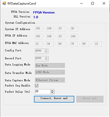
您好,我在两周前使用DCA1000+AWR1443采集数据可以正常检测FPGA2.8,而最近采集时SensorConfig选项卡SetUp DCA1000时FPGA弹窗检测不到FPGA版本号,如下图所示

命令串口打印信息如下
[10:33:34] [RadarAPI]: ar1.CaptureCardConfig_EthInit("192.168.33.30", "192.168.33.180", "12:34:56:78:90:12", 4096, 4098)
[10:33:34] [RadarAPI]: ar1.CaptureCardConfig_Mode(1, 1, 1, 2, 3, 30)
[10:33:34] [RadarAPI]: ar1.CaptureCardConfig_PacketDelay(25)
[10:33:35] [RadarAPI]: Sending fpga command to DCA1000
[10:33:45] [RadarAPI]:
[10:33:45] FPGA Configuration :
[10:33:45] Timeout Error! System disconnected
[10:33:45] [RadarAPI]: Sending record command to DCA1000
[10:33:55] [RadarAPI]:
[10:33:55] Configure Record :
[10:33:55] Timeout Error! System disconnected
[10:33:55] [RadarAPI]: ar1.GetCaptureCardFPGAVersion()
[10:33:55] [RadarAPI]: Sending fpga_version command to DCA1000
[10:34:05] [RadarAPI]:
[10:34:05]
[10:34:05] Unable to read FPGA Version. [error -5]
然后我不用手动配置,重新上电,仅配置Connection选项卡中Board Control中的Reset Control和RS232 Operations两项(不加载BSS和MSS固件),再跑
C:\ti\mmwave_studio_02_01_01_00\mmWaveStudio\Scripts\DataCaptureDemo_xWR.lua
命令窗口报错如下
[10:43:39] [RadarAPI]: ar1.LPModConfig(0, 0)
[10:43:39] [RadarAPI]: Status: Failed, Error Type: REGULAR ADC MODE NOT SUPPORTED IN 5 MHz PART VARIANT DEVICE
[10:43:39] Regualar mode Cfg failure
[10:43:39] [RadarAPI]: ar1.RfInit()
[10:43:39] RF Init async event received!
[10:43:39] [RadarAPI]: Time stamp, Temperture: 2436,29; APLL Status, Update: 1, 0; SynthVCO1 Status, Update: 1, 1; SynthVCO2 Status, Update: 1, 1; LODist Status, Update: 1, 1; RxADCDC Status, Update: 1, 1; HPFcutoff Status, Update: 1, 1; LPFcutoff Status, Update: 1, 1; PeakDetector Status, Update: 1, 1; TxPower Status, Update: 1, 1; RxGain Status, Update: 1, 1; TxPhase Status, Update: 0, 0; RxIQMM Status, Update: 1, 1;
[10:43:39] [RadarAPI]: Status: Passed
[10:43:39] RfInit Success
[10:43:40] [RadarAPI]: ar1.DataPathConfig(1, 1, 0)
[10:43:40] [RadarAPI]: Status: Passed
[10:43:40] DataPathConfig Success
[10:43:40] [RadarAPI]: ar1.LvdsClkConfig(1, 1)
[10:43:41] [RadarAPI]: Status: Passed
[10:43:41] LvdsClkConfig Success
[10:43:41] [RadarAPI]: ar1.LVDSLaneConfig(0, 1, 1, 1, 1, 1, 0, 0)
[10:43:41] [RadarAPI]: Status: Passed
[10:43:41] LVDSLaneConfig Success
[10:43:41] [RadarAPI]: ar1.SetTestSource(4, 3, 0, 0, 0, 0, -327, 0, -327, 327, 327, 327, -2.5, 327, 327, 0, 0, 0, 0, -327, 0, -327, 327, 327, 327, -95, 0, 0, 0.5, 0, 1, 0, 1.5, 0, 0, 0, 0, 0, 0, 0)
[10:43:41] [RadarAPI]: Status: Passed
[10:43:41] Test Source Configuration Success
[10:43:41] [RadarAPI]: ar1.ProfileConfig(0, 77, 100, 6, 60, 0, 0, 0, 0, 0, 0, 29.982, 0, 256, 10000, 0, 0, 30)
[10:43:41] Status: Failed, Error Type: SAMPLING RATE IS NOT WITHIN [2, 37.5] Msps
[10:43:41] ProfileConfig failure
[10:43:41] [RadarAPI]: ar1.ChirpConfig(0, 0, 0, 0, 0, 0, 0, 1, 1, 0)
[10:43:41] Status: Failed, Error Type: IF THE PROFILE CORRESPONDING TO PROFILE_INDEX IS NOT DEFINED
[10:43:41] ChirpConfig failure
[10:43:41] [RadarAPI]: ar1.EnableTestSource(1)
[10:43:41] [RadarAPI]: Status: Passed
[10:43:41] Enabling Test Source Success
[10:43:41]
[10:43:41] &&&&&&&&&&&&&&&&&&&&
[10:43:41] ***Script FAILED!***
[10:43:41] &&&&&&&&&&&&&&&&&&&&
[10:43:41] Exception message is:
[10:43:41] 索引超出了数组界限。
而后通过以下论坛中相似问题连接工程师Shine提供的方法
重新烧写FPGA,根据手册9 FPGA Programming中的安装步骤
For FPGA programming, install the Lattice Diamond Programmer standalone tool in the PC, as per the
following steps
1.Download the Lattice Diamond programmer tool, Windows version (Programmer Standalone 3.10 64-
bit for Windows) from the following link: www.latticesemi.com/programmer.
2.A new folder named lscc will be created at the path of installation.
Post installation steps
1.Connect the USB cable to the FPGA JTAG USB port (J4), and power on the board.
2.The FTDI cable driver is installed automatically. Otherwise, manually select the cable driver from the
installation path.
3.The device manager will recognize two COM ports, as shown in Figure 21.

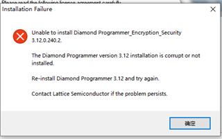
按照以上步骤操作,我下载到Programmer Standalone 3.12 64-bit for Windows,我的DCA1000EVM连J4之后也正常显示了两个串口,但是Lattice Diamond programmer安装不成功,显示如下(防火墙已关闭)

请问是什么原因呢?有没有什么解决方案呢?
