This thread has been locked.
If you have a related question, please click the "Ask a related question" button in the top right corner. The newly created question will be automatically linked to this question.
您好专家:
我使用的是 RTOS SDK 07.03和 EVM 板。
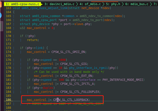
我们通过 RMII 接口连接 CPSW2G 端口1和 bcm89836 phy、并通过 MDIO C45协议配置 phy。 将 TDA4板直接连接到 PC、发现无法 ping PC。 通过 ifconifg、发现问题是由于 Mac 上没有 Rx 导致的。 设置 Mac loopback、ifconfig 仅具有 TX、无 Rx、这应该是 Mac 端的问题
我打开了 Mac 环回、在对 PC 执行几次 ping 操作后、ifconfig 如下所示:
寄存器转储如下所示:
期待您的回复
我将提供更多文件 dts 和主 c 文件
e2e.ti.com/.../3733.am65_2D00_cpsw_2D00_nuss.ce2e.ti.com/.../davinci_5F00_mdio.c
// SPDX-License-Identifier: GPL-2.0 /* * Copyright (C) 2019 Texas Instruments Incorporated - http://www.ti.com/ */ /dts-v1/; #include "k3-j721e-som-p0.dtsi" #include <dt-bindings/gpio/gpio.h> #include <dt-bindings/input/input.h> #include <dt-bindings/sound/ti-mcasp.h> #include <dt-bindings/net/ti-dp83867.h> / { chosen { stdout-path = "serial2:115200n8"; bootargs = "console=ttyS2,115200n8 earlycon=ns16550a,mmio32,0x02800000 root=/dev/mmcblk0p2 rw rootfstype=ext4 rootwait"; }; evm_12v0: fixedregulator-evm12v0 { /* main supply */ compatible = "regulator-fixed"; regulator-name = "evm_12v0"; regulator-min-microvolt = <12000000>; regulator-max-microvolt = <12000000>; regulator-always-on; regulator-boot-on; }; vsys_3v3: fixedregulator-vsys3v3 { /* Output of LMS140 */ compatible = "regulator-fixed"; regulator-name = "vsys_3v3"; regulator-min-microvolt = <3300000>; regulator-max-microvolt = <3300000>; vin-supply = <&evm_12v0>; regulator-always-on; regulator-boot-on; }; vsys_5v0: fixedregulator-vsys5v0 { /* Output of LM5140 */ compatible = "regulator-fixed"; regulator-name = "vsys_5v0"; regulator-min-microvolt = <5000000>; regulator-max-microvolt = <5000000>; vin-supply = <&evm_12v0>; regulator-always-on; regulator-boot-on; }; /* Used for 48KHz family */ pll4: pll4_fixed { #clock-cells = <0>; compatible = "fixed-clock"; clock-frequency = <1179648000>; }; /* Used for 44.1KHz family */ pll15: pll15_fixed { #clock-cells = <0>; compatible = "fixed-clock"; clock-frequency = <1083801600>; }; sound0: sound@0 { compatible = "ti,j721e-cpb-audio"; ti,model = "j721e-cpb-analog"; status = "disabled"; //ti,cpb-mcasp = <&mcasp10>; //ti,cpb-codec = <&pcm3168a_1>; clocks = <&pll4>, <&pll15>, <&k3_clks 184 1>, <&k3_clks 184 2>, <&k3_clks 184 4>, <&k3_clks 157 371>, <&k3_clks 157 400>, <&k3_clks 157 401>; clock-names = "pll4", "pll15", "cpb-mcasp", "cpb-mcasp-48000", "cpb-mcasp-44100", "audio-refclk2", "audio-refclk2-48000", "audio-refclk2-44100"; }; vdd_mmc1: fixedregulator-sd { compatible = "regulator-fixed"; regulator-name = "vdd_mmc1"; regulator-min-microvolt = <3300000>; regulator-max-microvolt = <3300000>; regulator-boot-on; enable-active-high; vin-supply = <&vsys_3v3>; //gpio = <&exp2 2 GPIO_ACTIVE_HIGH>; }; vdd_sd_dv_alt: gpio-regulator-TLV71033 { compatible = "regulator-gpio"; pinctrl-names = "default"; pinctrl-0 = <&vdd_sd_dv_alt_pins_idc>; regulator-name = "tlv71033"; regulator-min-microvolt = <1800000>; regulator-max-microvolt = <3300000>; regulator-boot-on; vin-supply = <&vsys_5v0>; gpios = <&main_gpio0 5 GPIO_ACTIVE_HIGH>; states = <1800000 0x0 3300000 0x1>; }; cpsw9g_virt_mac: main_r5fss_cpsw9g_virt_mac0 { compatible = "ti,j721e-cpsw-virt-mac"; dma-coherent; ti,psil-base = <0x4a00>; ti,remote-name = "mpu_1_0_ethswitch-device-0"; dmas = <&main_udmap 0xca00>, <&main_udmap 0xca01>, <&main_udmap 0xca02>, <&main_udmap 0xca03>, <&main_udmap 0xca04>, <&main_udmap 0xca05>, <&main_udmap 0xca06>, <&main_udmap 0xca07>, <&main_udmap 0x4a00>; dma-names = "tx0", "tx1", "tx2", "tx3", "tx4", "tx5", "tx6", "tx7", "rx"; virt_emac_port { ti,label = "virt-port"; /* local-mac-address = [0 0 0 0 0 0]; */ }; }; dp0: connector { compatible = "dp-connector"; label = "DP0"; port { dp_connector_in: endpoint { remote-endpoint = <&dp_bridge_output>; }; }; }; clk_ov5640_fixed: ov5640-xclk { compatible = "fixed-clock"; #clock-cells = <0>; clock-frequency = <25000000>; }; }; &main_pmx0 { dp0_pins_default: dp0_pins_default { pinctrl-single,pins = < J721E_IOPAD(0x1c4, PIN_INPUT, 5) /* SPI0_CS1.DP0_HPD */ >; }; main_i2c1_exp4_pins_default: main-i2c1-exp4-pins-default { pinctrl-single,pins = < J721E_IOPAD(0x230, PIN_INPUT, 7) /* (U2) ECAP0_IN_APWM_OUT.GPIO1_11 */ >; }; main_i2c0_pins_default: main-i2c0-pins-default { pinctrl-single,pins = < J721E_IOPAD(0x220, PIN_INPUT_PULLUP, 0) /* (AC5) I2C0_SCL */ J721E_IOPAD(0x224, PIN_INPUT_PULLUP, 0) /* (AA5) I2C0_SDA */ >; }; main_i2c1_pins_default: main-i2c1-pins-default { pinctrl-single,pins = < J721E_IOPAD(0x228, PIN_INPUT_PULLUP, 0) /* (Y6) I2C1_SCL */ J721E_IOPAD(0x22c, PIN_INPUT_PULLUP, 0) /* (AA6) I2C1_SDA */ >; }; main_i2c3_pins_default: main-i2c3-pins-default { pinctrl-single,pins = < J721E_IOPAD(0x270, PIN_INPUT_PULLUP, 4) /* (T26) MMC2_CLK.I2C3_SCL */ J721E_IOPAD(0x274, PIN_INPUT_PULLUP, 4) /* (T25) MMC2_CMD.I2C3_SDA */ >; }; main_i2c6_pins_default: main-i2c6-pins-default { pinctrl-single,pins = < J721E_IOPAD(0x1d0, PIN_INPUT_PULLUP, 2) /* (AA3) SPI0_D1.I2C6_SCL */ J721E_IOPAD(0x1e4, PIN_INPUT_PULLUP, 2) /* (Y2) SPI1_D1.I2C6_SDA */ >; }; mcasp10_pins_default: mcasp10_pins_default { pinctrl-single,pins = < J721E_IOPAD(0x158, PIN_OUTPUT_PULLDOWN, 12) /* (U23) RGMII5_TX_CTL.MCASP10_ACLKX */ J721E_IOPAD(0x15c, PIN_OUTPUT_PULLDOWN, 12) /* (U26) RGMII5_RX_CTL.MCASP10_AFSX */ J721E_IOPAD(0x160, PIN_OUTPUT_PULLDOWN, 12) /* (V28) RGMII5_TD3.MCASP10_AXR0 */ J721E_IOPAD(0x164, PIN_OUTPUT_PULLDOWN, 12) /* (V29) RGMII5_TD2.MCASP10_AXR1 */ J721E_IOPAD(0x170, PIN_OUTPUT_PULLDOWN, 12) /* (U29) RGMII5_TXC.MCASP10_AXR2 */ J721E_IOPAD(0x174, PIN_OUTPUT_PULLDOWN, 12) /* (U25) RGMII5_RXC.MCASP10_AXR3 */ J721E_IOPAD(0x198, PIN_INPUT_PULLDOWN, 12) /* (V25) RGMII6_TD1.MCASP10_AXR4 */ J721E_IOPAD(0x19c, PIN_INPUT_PULLDOWN, 12) /* (W27) RGMII6_TD0.MCASP10_AXR5 */ J721E_IOPAD(0x1a0, PIN_INPUT_PULLDOWN, 12) /* (W29) RGMII6_TXC.MCASP10_AXR6 */ >; }; audi_ext_refclk2_pins_default: audi_ext_refclk2_pins_default { pinctrl-single,pins = < J721E_IOPAD(0x1a4, PIN_OUTPUT, 3) /* (W26) RGMII6_RXC.AUDIO_EXT_REFCLK2 */ >; }; main_mmc1_pins_default: main_mmc1_pins_default { pinctrl-single,pins = < J721E_IOPAD(0x254, PIN_INPUT, 0) /* (R29) MMC1_CMD */ J721E_IOPAD(0x250, PIN_INPUT, 0) /* (P25) MMC1_CLK */ J721E_IOPAD(0x2ac, PIN_INPUT, 0) /* (P25) MMC1_CLKLB */ J721E_IOPAD(0x24c, PIN_INPUT, 0) /* (R24) MMC1_DAT0 */ J721E_IOPAD(0x248, PIN_INPUT, 0) /* (P24) MMC1_DAT1 */ J721E_IOPAD(0x244, PIN_INPUT, 0) /* (R25) MMC1_DAT2 */ J721E_IOPAD(0x240, PIN_INPUT, 0) /* (R26) MMC1_DAT3 */ J721E_IOPAD(0x258, PIN_INPUT, 0) /* (P23) MMC1_SDCD */ J721E_IOPAD(0x25c, PIN_INPUT, 0) /* (R28) MMC1_SDWP */ >; }; vdd_sd_dv_alt_pins_default: vdd_sd_dv_alt_pins_default { pinctrl-single,pins = < J721E_IOPAD(0x1d8, PIN_INPUT, 7) /* (W4) SPI1_CS1.GPIO0_117 */ >; }; vdd_sd_dv_alt_pins_idc: vdd_sd_dv_alt_pins_idc { pinctrl-single,pins = < J721E_IOPAD(0x014, PIN_INPUT, 7) /* (AH23) GPIO0_5 */ >; }; main_usbss0_pins_default: main_usbss0_pins_default { pinctrl-single,pins = < J721E_IOPAD(0x290, PIN_OUTPUT, 0) /* (U6) USB0_DRVVBUS */ >; }; main_usbss1_pins_default: main_usbss1_pins_default { }; // enable main_mcan0 in PT1 : Rader main_mcan0_pins_default: main_mcan0_pins_default { pinctrl-single,pins = < J721E_IOPAD(0x208, PIN_INPUT, 0) /* (W5) MCAN0_RX : GPIO1_1 */ J721E_IOPAD(0x20c, PIN_OUTPUT, 0) /* (W6) MCAN0_TX : GPIO1_2 */ >; }; // enable main_mcan1 in PT1 : IFC main_mcan1_pins_default: main_mcan1_pins_default { pinctrl-single,pins = < J721E_IOPAD(0x210, PIN_INPUT, 0) /* (W3) MCAN1_RX : GPIO1_3 */ J721E_IOPAD(0x214, PIN_OUTPUT, 0) /* (V4) MCAN1_TX : GPIO1_4 */ >; }; // enable main_mcan2 in PT1: Rader main_mcan2_pins_default: main_mcan2_pins_default { pinctrl-single,pins = < J721E_IOPAD(0x1f0, PIN_INPUT, 3) /* (AC2) MCAN2_RX : GPIO0_123 */ J721E_IOPAD(0x1f4, PIN_OUTPUT, 3) /* (AB1) MCAN2_TX : GPIO0_124 */ >; }; }; &wkup_pmx0 { sw11_button_pins_default: sw11_button_pins_default { pinctrl-single,pins = < J721E_WKUP_IOPAD(0xcc, PIN_INPUT, 7) /* (G28) WKUP_GPIO0_7 */ >; }; mcu_fss0_ospi1_pins_default: mcu-fss0-ospi1-pins-default { pinctrl-single,pins = < J721E_WKUP_IOPAD(0x34, PIN_OUTPUT, 0) /* (F22) MCU_OSPI1_CLK */ J721E_WKUP_IOPAD(0x50, PIN_OUTPUT, 0) /* (C22) MCU_OSPI1_CSn0 */ J721E_WKUP_IOPAD(0x40, PIN_INPUT, 0) /* (D22) MCU_OSPI1_D0 */ J721E_WKUP_IOPAD(0x44, PIN_INPUT, 0) /* (G22) MCU_OSPI1_D1 */ J721E_WKUP_IOPAD(0x48, PIN_INPUT, 0) /* (D23) MCU_OSPI1_D2 */ J721E_WKUP_IOPAD(0x4c, PIN_INPUT, 0) /* (C23) MCU_OSPI1_D3 */ J721E_WKUP_IOPAD(0x3c, PIN_INPUT, 0) /* (B23) MCU_OSPI1_DQS */ J721E_WKUP_IOPAD(0x38, PIN_INPUT, 0) /* (A23) MCU_OSPI1_LBCLKO */ >; }; }; &wkup_pmx0 { mcu_cpsw_pins_default: mcu_cpsw_pins_default { pinctrl-single,pins = < J721E_WKUP_IOPAD(0x58, PIN_INPUT, 1) /* (B27) MCU_RGMII1_TX_CTL.MCU_RMII1_CRS_DV */ J721E_WKUP_IOPAD(0x74, PIN_INPUT, 1) /* (C24) MCU_RGMII1_RXC.MCU_RMII1_REF_CLK */ J721E_WKUP_IOPAD(0x84, PIN_INPUT, 1) /* (B24) MCU_RGMII1_RD0.MCU_RMII1_RXD0 */ J721E_WKUP_IOPAD(0x80, PIN_INPUT, 1) /* (A24) MCU_RGMII1_RD1.MCU_RMII1_RXD1 */ J721E_WKUP_IOPAD(0x5c, PIN_INPUT, 1) /* (C25) MCU_RGMII1_RX_CTL.MCU_RMII1_RX_ER */ J721E_WKUP_IOPAD(0x6c, PIN_OUTPUT, 1) /* (B25) MCU_RGMII1_TD0.MCU_RMII1_TXD0 */ J721E_WKUP_IOPAD(0x68, PIN_OUTPUT, 1) /* (A26) MCU_RGMII1_TD1.MCU_RMII1_TXD1 */ J721E_WKUP_IOPAD(0x70, PIN_OUTPUT, 1) /* (B26) MCU_RGMII1_TXC.MCU_RMII1_TX_EN */ >; }; mcu_mdio_pins_default: mcu_mdio1_pins_default { pinctrl-single,pins = < J721E_WKUP_IOPAD(0x008c, PIN_OUTPUT, 0) /* MCU_MDIO0_MDC */ J721E_WKUP_IOPAD(0x0088, PIN_INPUT, 0) /* MCU_MDIO0_MDIO */ >; }; mcu_mcan0_pins_default: mcu-mcan0-pins-default { pinctrl-single,pins = < J721E_WKUP_IOPAD(0xac, PIN_INPUT, 0) /* (C29) MCU_MCAN0_RX */ J721E_WKUP_IOPAD(0xa8, PIN_OUTPUT, 0) /* (D29) MCU_MCAN0_TX */ >; }; mcu_mcan0_gpio_pins_default: mcu-mcan0-gpio-pins-default { pinctrl-single,pins = < J721E_WKUP_IOPAD(0xb0, PIN_INPUT, 7) /* (F26) WKUP_GPIO0_0 */ J721E_WKUP_IOPAD(0x98, PIN_INPUT, 7) /* (E28) MCU_SPI0_D1.WKUP_GPIO0_54 */ >; }; mcu_mcan1_pins_default: mcu-mcan1-pins-default { pinctrl-single,pins = < J721E_WKUP_IOPAD(0xc4, PIN_INPUT, 0) /* (G24) WKUP_GPIO0_5.MCU_MCAN1_RX */ J721E_WKUP_IOPAD(0xc0, PIN_OUTPUT, 0) /* (G25) WKUP_GPIO0_4.MCU_MCAN1_TX */ >; }; mcu_mcan1_gpio_pins_default: mcu-mcan1-gpio-pins-default { pinctrl-single,pins = < J721E_WKUP_IOPAD(0xb8, PIN_INPUT, 7) /* (F28) WKUP_GPIO0_2 */ >; }; }; &wkup_uart0 { /* Wakeup UART is used by System firmware */ status = "disabled"; }; &main_uart0 { power-domains = <&k3_pds 146 TI_SCI_PD_SHARED>; }; &main_uart1 { /* UART not brought out */ status = "disabled"; }; &main_uart3 { /* UART not brought out */ status = "disabled"; }; &main_uart4 { /* UART not brought out */ status = "disabled"; }; &main_uart5 { /* UART not brought out */ status = "disabled"; }; &main_uart6 { /* UART not brought out */ status = "disabled"; }; &main_uart7 { /* UART not brought out */ status = "disabled"; }; &main_uart8 { /* UART not brought out */ status = "disabled"; }; &main_uart9 { /* UART not brought out */ status = "disabled"; }; &main_gpio2 { status = "disabled"; }; &main_gpio3 { status = "disabled"; }; &main_gpio4 { status = "disabled"; }; &main_gpio5 { status = "disabled"; }; &main_gpio6 { status = "disabled"; }; &main_gpio7 { status = "disabled"; }; &wkup_gpio1 { status = "disabled"; }; &mailbox0_cluster0 { interrupts = <436>; mbox_mcu_r5fss0_core0: mbox-mcu-r5fss0-core0 { ti,mbox-rx = <0 0 0>; ti,mbox-tx = <1 0 0>; }; mbox_mcu_r5fss0_core1: mbox-mcu-r5fss0-core1 { ti,mbox-rx = <2 0 0>; ti,mbox-tx = <3 0 0>; }; }; &mailbox0_cluster1 { interrupts = <432>; mbox_main_r5fss0_core0: mbox-main-r5fss0-core0 { ti,mbox-rx = <0 0 0>; ti,mbox-tx = <1 0 0>; }; mbox_main_r5fss0_core1: mbox-main-r5fss0-core1 { ti,mbox-rx = <2 0 0>; ti,mbox-tx = <3 0 0>; }; }; &mailbox0_cluster2 { interrupts = <428>; mbox_main_r5fss1_core0: mbox-main-r5fss1-core0 { ti,mbox-rx = <0 0 0>; ti,mbox-tx = <1 0 0>; }; mbox_main_r5fss1_core1: mbox-main-r5fss1-core1 { ti,mbox-rx = <2 0 0>; ti,mbox-tx = <3 0 0>; }; }; &mailbox0_cluster3 { interrupts = <424>; mbox_c66_0: mbox-c66-0 { ti,mbox-rx = <0 0 0>; ti,mbox-tx = <1 0 0>; }; mbox_c66_1: mbox-c66-1 { ti,mbox-rx = <2 0 0>; ti,mbox-tx = <3 0 0>; }; }; &mailbox0_cluster4 { interrupts = <420>; mbox_c71_0: mbox-c71-0 { ti,mbox-rx = <0 0 0>; ti,mbox-tx = <1 0 0>; }; }; &mailbox0_cluster5 { status = "disabled"; }; &mailbox0_cluster6 { status = "disabled"; }; &mailbox0_cluster7 { status = "disabled"; }; &mailbox0_cluster8 { status = "disabled"; }; &mailbox0_cluster9 { status = "disabled"; }; &mailbox0_cluster10 { status = "disabled"; }; &mailbox0_cluster11 { status = "disabled"; }; &mcu_r5fss0_core0 { mboxes = <&mailbox0_cluster0 &mbox_mcu_r5fss0_core0>; }; &mcu_r5fss0_core1 { mboxes = <&mailbox0_cluster0 &mbox_mcu_r5fss0_core1>; }; &main_r5fss0_core0 { mboxes = <&mailbox0_cluster1 &mbox_main_r5fss0_core0>; }; &main_r5fss0_core1 { mboxes = <&mailbox0_cluster1 &mbox_main_r5fss0_core1>; }; &main_r5fss1_core0 { mboxes = <&mailbox0_cluster2 &mbox_main_r5fss1_core0>; }; &main_r5fss1_core1 { mboxes = <&mailbox0_cluster2 &mbox_main_r5fss1_core1>; }; &c66_0 { mboxes = <&mailbox0_cluster3 &mbox_c66_0>; }; &c66_1 { mboxes = <&mailbox0_cluster3 &mbox_c66_1>; }; &c71_0 { mboxes = <&mailbox0_cluster4 &mbox_c71_0>; }; &ospi1 { pinctrl-names = "default"; pinctrl-0 = <&mcu_fss0_ospi1_pins_default>; flash@0{ compatible = "jedec,spi-nor"; reg = <0x0>; spi-tx-bus-width = <1>; spi-rx-bus-width = <4>; spi-max-frequency = <40000000>; cdns,tshsl-ns = <60>; cdns,tsd2d-ns = <60>; cdns,tchsh-ns = <60>; cdns,tslch-ns = <60>; cdns,read-delay = <2>; #address-cells = <1>; #size-cells = <1>; }; }; &tscadc0 { status = "disabled"; adc { ti,adc-channels = <0 1 2 3 4 5 6 7>; }; }; &tscadc1 { status = "disabled"; adc { ti,adc-channels = <0 1 2 3 4 5 6 7>; }; }; &dss { status = "ok"; }; &dss_ports { #address-cells = <1>; #size-cells = <0>; port@0 { reg = <0>; dpi_out_real0: endpoint { remote-endpoint = <&dp_bridge_input>; }; }; }; &mhdp { status = "ok"; pinctrl-names = "default"; pinctrl-0 = <&dp0_pins_default>; }; &dp0_ports { #address-cells = <1>; #size-cells = <0>; port@0 { reg = <0>; dp_bridge_input: endpoint { remote-endpoint = <&dpi_out_real0>; }; }; port@1 { reg = <1>; dp_bridge_output: endpoint { remote-endpoint = <&dp_connector_in>; }; }; }; &k3_clks { /* Confiure AUDIO_EXT_REFCLK2 pin as output */ pinctrl-names = "default"; pinctrl-0 = <&audi_ext_refclk2_pins_default>; }; &mcu_cpsw { pinctrl-names = "default"; pinctrl-0 = <&mcu_cpsw_pins_default &mcu_mdio_pins_default>; }; &davinci_mdio { phy0: ethernet-phy@0 { compatible = "ethernet-phy-ieee802.3-c45"; reg = <0>; ti,rx-internal-delay = <DP83867_RGMIIDCTL_2_00_NS>; ti,fifo-depth = <DP83867_PHYCR_FIFO_DEPTH_4_B_NIB>; }; }; &cpsw_port1 { phy-mode = "rmii"; phy-handle = <&phy0>; }; &main_sdhci0 { /* eMMC */ non-removable; ti,driver-strength-ohm = <50>; disable-wp; }; &main_sdhci1 { /* SD/MMC */ //vmmc-supply = <&vdd_mmc1>; vmmc-supply = <&vsys_3v3>; vqmmc-supply = <&vdd_sd_dv_alt>; pinctrl-names = "default"; pinctrl-0 = <&main_mmc1_pins_default>; disable-wp; }; &main_sdhci2 { /* Unused */ status = "disabled"; }; &serdes_wiz0 { status = "disabled"; }; &serdes0 { serdes0_pcie_link: link@0 { reg = <0>; cdns,num-lanes = <1>; #phy-cells = <0>; cdns,phy-type = <PHY_TYPE_PCIE>; resets = <&serdes_wiz0 1>; status = "disabled"; }; }; &serdes1 { serdes1_pcie_link: link@0 { reg = <0>; cdns,num-lanes = <2>; #phy-cells = <0>; cdns,phy-type = <PHY_TYPE_PCIE>; resets = <&serdes_wiz1 1>, <&serdes_wiz1 2>; }; }; &serdes2 { serdes2_pcie_link: link@0 { reg = <0>; cdns,num-lanes = <2>; #phy-cells = <0>; cdns,phy-type = <PHY_TYPE_PCIE>; resets = <&serdes_wiz2 1>, <&serdes_wiz2 2>; }; }; &pcie0_rc { status = "disabled"; //reset-gpios = <&exp1 6 GPIO_ACTIVE_HIGH>; phys = <&serdes0_pcie_link>; phy-names = "pcie_phy"; num-lanes = <1>; }; &pcie1_rc { status = "disabled"; //reset-gpios = <&exp1 2 GPIO_ACTIVE_HIGH>; phys = <&serdes1_pcie_link>; phy-names = "pcie_phy"; num-lanes = <2>; }; &pcie2_rc { status = "disabled"; //reset-gpios = <&exp2 20 GPIO_ACTIVE_HIGH>; phys = <&serdes2_pcie_link>; phy-names = "pcie_phy"; num-lanes = <2>; }; &pcie0_ep { phys = <&serdes0_pcie_link>; phy-names = "pcie_phy"; num-lanes = <1>; status = "disabled"; }; &pcie1_ep { phys = <&serdes1_pcie_link>; phy-names = "pcie_phy"; num-lanes = <2>; status = "disabled"; }; &pcie2_ep { phys = <&serdes2_pcie_link>; phy-names = "pcie_phy"; num-lanes = <2>; status = "disabled"; }; &pcie3_rc { status = "disabled"; }; &pcie3_ep { status = "disabled"; }; &usb_serdes_mux { idle-states = <1>, <0>; /* USB0 to SERDES3, USB1 to SERDES1 */ }; &serdes_ln_ctrl { idle-states = <SERDES0_LANE0_PCIE0_LANE0>, <SERDES0_LANE1_PCIE0_LANE1>, <SERDES1_LANE0_PCIE1_LANE0>, <SERDES1_LANE1_PCIE1_LANE1>, <SERDES2_LANE0_PCIE2_LANE0>, <SERDES2_LANE1_PCIE2_LANE1>, <SERDES3_LANE0_USB3_0_SWAP>, <SERDES3_LANE1_USB3_0>, <SERDES4_LANE0_EDP_LANE0>, <SERDES4_LANE1_EDP_LANE1>, <SERDES4_LANE2_EDP_LANE2>, <SERDES4_LANE3_EDP_LANE3>; }; &serdes_wiz3 { typec-dir-gpios = <&main_gpio1 3 GPIO_ACTIVE_LOW>; typec-dir-debounce-ms = <700>; /* TUSB321, tCCB_DEFAULT 133 ms */ }; &serdes3 { serdes3_usb_link: link@0 { reg = <0>; cdns,num-lanes = <2>; #phy-cells = <0>; cdns,phy-type = <PHY_TYPE_USB3>; resets = <&serdes_wiz3 1>, <&serdes_wiz3 2>; }; }; &usbss0 { status = "disabled"; pinctrl-names = "default"; pinctrl-0 = <&main_usbss0_pins_default>; ti,vbus-divider; }; &usb0 { status = "disabled"; dr_mode = "otg"; maximum-speed = "super-speed"; phys = <&serdes3_usb_link>; phy-names = "cdns3,usb3-phy"; }; &usbss1 { status = "disabled"; pinctrl-names = "default"; pinctrl-0 = <&main_usbss1_pins_default>; ti,usb2-only; }; &usb1 { status = "disabled"; dr_mode = "host"; maximum-speed = "high-speed"; }; /* uart2 assigned to cpsw9g eth-switch fw running on remote CPU core */ &main_uart2 { status = "disabled"; }; /*&mcu_mcan0 { status = "disabled"; pinctrl-names = "default"; pinctrl-0 = <&mcu_mcan0_pins_default &mcu_mcan0_gpio_pins_default>; stb-gpios = <&wkup_gpio0 54 GPIO_ACTIVE_HIGH>; en-gpios = <&wkup_gpio0 0 GPIO_ACTIVE_HIGH>; can-transceiver { max-bitrate = <5000000>; }; }; &mcu_mcan1 { status = "disabled"; pinctrl-names = "default"; pinctrl-0 = <&mcu_mcan1_pins_default &mcu_mcan1_gpio_pins_default>; stb-gpios = <&wkup_gpio0 2 GPIO_ACTIVE_LOW>; can-transceiver { max-bitrate = <5000000>; }; }; */ &main_mcan0 { status = "okay"; pinctrl-names = "default"; pinctrl-0 = <&main_mcan0_pins_default>; can-transceiver { max-bitrate = <5000000>; }; }; &main_mcan1 { status = "okay"; pinctrl-names = "default"; pinctrl-0 = <&main_mcan1_pins_default>; can-transceiver { max-bitrate = <5000000>; }; }; &main_mcan2 { status = "okay"; pinctrl-names = "default"; pinctrl-0 = <&main_mcan2_pins_default>; can-transceiver { max-bitrate = <5000000>; }; }; &main_mcan3 { status = "disabled"; }; &main_mcan4 { status = "disabled"; }; &main_mcan5 { status = "disabled"; }; &main_mcan6 { status = "disabled"; }; &main_mcan7 { status = "disabled"; }; &main_mcan8 { status = "disabled"; }; &main_mcan9 { status = "disabled"; }; &main_mcan10 { status = "disabled"; }; &main_mcan11 { status = "disabled"; }; &main_mcan12 { status = "disabled"; }; &main_mcan13 { status = "disabled"; }; &csi2_0 { csi2rx0_in_sensor: endpoint { // remote-endpoint = <&csi2_cam0>; bus-type = <4>; /* CSI2 DPHY. */ clock-lanes = <0>; data-lanes = <1 2>; }; }; &main_i2c0 { status = "disabled"; }; &main_i2c6 { status = "disabled"; }; &serdes_wiz4 { status = "disabled"; }; &mhdp { status = "disabled"; }; &dss { status = "disabled"; }; &main_i2c1 { status = "disabled"; }; &ti_csi2rx0 { status = "disabled"; }; &d5520 { status = "disabled"; }; &vxe384 { status = "disabled"; };
// SPDX-License-Identifier: GPL-2.0 /* * Device Tree Source for J721E SoC Family MCU/WAKEUP Domain peripherals * * Copyright (C) 2016-2019 Texas Instruments Incorporated - http://www.ti.com/ */ &cbass_mcu_wakeup { dmsc: dmsc@44083000 { compatible = "ti,k2g-sci"; ti,host-id = <12>; mbox-names = "rx", "tx"; mboxes= <&secure_proxy_main 11>, <&secure_proxy_main 13>; reg-names = "debug_messages"; reg = <0x00 0x44083000 0x0 0x1000>; k3_pds: power-controller { compatible = "ti,sci-pm-domain"; #power-domain-cells = <2>; }; k3_clks: clocks { compatible = "ti,k2g-sci-clk"; #clock-cells = <2>; }; k3_reset: reset-controller { compatible = "ti,sci-reset"; #reset-cells = <2>; }; }; mcu_conf: scm_conf@40f00000 { compatible = "syscon", "simple-mfd"; reg = <0x0 0x40f00000 0x0 0x20000>; #address-cells = <1>; #size-cells = <1>; ranges = <0x0 0x0 0x40f00000 0x20000>; phy_gmii_sel: phy@4040 { compatible = "ti,am654-phy-gmii-sel"; reg = <0x4040 0x4>; #phy-cells = <1>; }; }; chipid@43000014 { compatible = "ti,am654-chipid"; reg = <0x0 0x43000014 0x0 0x4>; }; wkup_pmx0: pinmux@4301c000 { compatible = "pinctrl-single"; /* Proxy 0 addressing */ reg = <0x00 0x4301c000 0x00 0x178>; #pinctrl-cells = <1>; pinctrl-single,register-width = <32>; pinctrl-single,function-mask = <0xffffffff>; }; mcu_ram: sram@41c00000 { compatible = "mmio-sram"; reg = <0x00 0x41c00000 0x00 0x100000>; ranges = <0x0 0x00 0x41c00000 0x100000>; #address-cells = <1>; #size-cells = <1>; }; wkup_uart0: serial@42300000 { status = "disabled"; compatible = "ti,j721e-uart", "ti,am654-uart"; reg = <0x00 0x42300000 0x00 0x100>; reg-shift = <2>; reg-io-width = <4>; interrupts = <GIC_SPI 897 IRQ_TYPE_LEVEL_HIGH>; clock-frequency = <48000000>; current-speed = <115200>; power-domains = <&k3_pds 287 TI_SCI_PD_EXCLUSIVE>; clocks = <&k3_clks 287 0>; clock-names = "fclk"; }; mcu_uart0: serial@40a00000 { status = "disabled"; compatible = "ti,j721e-uart", "ti,am654-uart"; reg = <0x00 0x40a00000 0x00 0x100>; reg-shift = <2>; reg-io-width = <4>; interrupts = <GIC_SPI 846 IRQ_TYPE_LEVEL_HIGH>; clock-frequency = <96000000>; current-speed = <115200>; power-domains = <&k3_pds 149 TI_SCI_PD_EXCLUSIVE>; clocks = <&k3_clks 149 0>; clock-names = "fclk"; }; wkup_gpio_intr: interrupt-controller2 { compatible = "ti,sci-intr"; ti,intr-trigger-type = <1>; interrupt-controller; interrupt-parent = <&gic500>; #interrupt-cells = <1>; ti,sci = <&dmsc>; ti,sci-dev-id = <137>; ti,interrupt-ranges = <16 960 16>; }; wkup_gpio0: gpio@42110000 { compatible = "ti,j721e-gpio", "ti,keystone-gpio"; reg = <0x0 0x42110000 0x0 0x100>; gpio-controller; #gpio-cells = <2>; interrupt-parent = <&wkup_gpio_intr>; interrupts = <103>, <104>, <105>, <106>, <107>, <108>; interrupt-controller; #interrupt-cells = <2>; ti,ngpio = <84>; ti,davinci-gpio-unbanked = <0>; power-domains = <&k3_pds 113 TI_SCI_PD_EXCLUSIVE>; clocks = <&k3_clks 113 0>; clock-names = "gpio"; }; wkup_gpio1: gpio@42100000 { compatible = "ti,j721e-gpio", "ti,keystone-gpio"; reg = <0x0 0x42100000 0x0 0x100>; gpio-controller; #gpio-cells = <2>; interrupt-parent = <&wkup_gpio_intr>; interrupts = <112>, <113>, <114>, <115>, <116>, <117>; interrupt-controller; #interrupt-cells = <2>; ti,ngpio = <84>; ti,davinci-gpio-unbanked = <0>; power-domains = <&k3_pds 114 TI_SCI_PD_EXCLUSIVE>; clocks = <&k3_clks 114 0>; clock-names = "gpio"; }; mcu_i2c0: i2c@40b00000 { status = "disabled"; compatible = "ti,j721e-i2c", "ti,omap4-i2c"; reg = <0x0 0x40b00000 0x0 0x100>; interrupts = <GIC_SPI 852 IRQ_TYPE_LEVEL_HIGH>; #address-cells = <1>; #size-cells = <0>; clock-names = "fck"; clocks = <&k3_clks 194 0>; power-domains = <&k3_pds 194 TI_SCI_PD_EXCLUSIVE>; }; fss: fss@47000000 { compatible = "simple-bus"; reg = <0x0 0x47000000 0x0 0x100>; #address-cells = <2>; #size-cells = <2>; ranges; ospi0: spi@47040000 { status = "disabled"; compatible = "ti,am654-ospi"; reg = <0x0 0x47040000 0x0 0x100>, <0x5 0x00000000 0x1 0x0000000>; interrupts = <GIC_SPI 840 IRQ_TYPE_LEVEL_HIGH>; cdns,fifo-depth = <256>; cdns,fifo-width = <4>; cdns,trigger-address = <0x0>; clocks = <&k3_clks 103 0>; assigned-clocks = <&k3_clks 103 0>; assigned-clock-parents = <&k3_clks 103 2>; assigned-clock-rates = <166666666>; power-domains = <&k3_pds 103 TI_SCI_PD_EXCLUSIVE>; #address-cells = <1>; #size-cells = <0>; }; ospi1: spi@47050000 { status = "disabled"; compatible = "ti,am654-ospi"; reg = <0x0 0x47050000 0x0 0x100>, <0x7 0x00000000 0x1 0x00000000>; interrupts = <GIC_SPI 841 IRQ_TYPE_LEVEL_HIGH>; cdns,fifo-depth = <256>; cdns,fifo-width = <4>; cdns,trigger-address = <0x0>; clocks = <&k3_clks 104 0>; power-domains = <&k3_pds 104 TI_SCI_PD_EXCLUSIVE>; #address-cells = <1>; #size-cells = <0>; }; }; tscadc0: tscadc@40200000 { status = "disabled"; compatible = "ti,am3359-tscadc"; reg = <0x0 0x40200000 0x0 0x1000>; interrupts = <GIC_SPI 860 IRQ_TYPE_LEVEL_HIGH>; power-domains = <&k3_pds 0 TI_SCI_PD_EXCLUSIVE>; clocks = <&k3_clks 0 1>; assigned-clocks = <&k3_clks 0 3>; assigned-clock-rates = <60000000>; clock-names = "adc_tsc_fck"; adc { #io-channel-cells = <1>; compatible = "ti,am3359-adc"; }; }; tscadc1: tscadc@40210000 { status = "disabled"; compatible = "ti,am3359-tscadc"; reg = <0x0 0x40210000 0x0 0x1000>; interrupts = <GIC_SPI 861 IRQ_TYPE_LEVEL_HIGH>; power-domains = <&k3_pds 1 TI_SCI_PD_EXCLUSIVE>; clocks = <&k3_clks 1 1>; assigned-clocks = <&k3_clks 1 3>; assigned-clock-rates = <60000000>; clock-names = "adc_tsc_fck"; adc { #io-channel-cells = <1>; compatible = "ti,am3359-adc"; }; }; cbass_mcu_navss: navss@28380000 { compatible = "simple-mfd"; #address-cells = <2>; #size-cells = <2>; ranges; dma-coherent; dma-ranges; ti,sci-dev-id = <232>; mcu_ringacc: ringacc@2b800000 { compatible = "ti,am654-navss-ringacc"; reg = <0x0 0x2b800000 0x0 0x400000>, <0x0 0x2b000000 0x0 0x400000>, <0x0 0x28590000 0x0 0x100>, <0x0 0x2a500000 0x0 0x40000>; reg-names = "rt", "fifos", "proxy_gcfg", "proxy_target"; ti,num-rings = <286>; ti,sci-rm-range-gp-rings = <0x1>; /* GP ring range */ ti,sci = <&dmsc>; ti,sci-dev-id = <235>; msi-parent = <&main_udmass_inta>; }; mcu_udmap: dma-controller@285c0000 { compatible = "ti,j721e-navss-mcu-udmap"; reg = <0x0 0x285c0000 0x0 0x100>, <0x0 0x2a800000 0x0 0x40000>, <0x0 0x2aa00000 0x0 0x40000>; reg-names = "gcfg", "rchanrt", "tchanrt"; msi-parent = <&main_udmass_inta>; #dma-cells = <1>; ti,sci = <&dmsc>; ti,sci-dev-id = <236>; ti,ringacc = <&mcu_ringacc>; ti,sci-rm-range-tchan = <0x0d>, /* TX_CHAN */ <0x0f>; /* TX_HCHAN */ ti,sci-rm-range-rchan = <0x0a>, /* RX_CHAN */ <0x0b>; /* RX_HCHAN */ ti,sci-rm-range-rflow = <0x00>; /* GP RFLOW */ }; }; mcu_cpsw: ethernet@46000000 { compatible = "ti,j721e-cpsw-nuss"; #address-cells = <2>; #size-cells = <2>; reg = <0x0 0x46000000 0x0 0x200000>; reg-names = "cpsw_nuss"; ranges = <0x0 0x0 0x0 0x46000000 0x0 0x200000>; dma-coherent; clocks = <&k3_clks 18 22>; clock-names = "fck"; power-domains = <&k3_pds 18 TI_SCI_PD_EXCLUSIVE>; dmas = <&mcu_udmap 0xf000>, <&mcu_udmap 0xf001>, <&mcu_udmap 0xf002>, <&mcu_udmap 0xf003>, <&mcu_udmap 0xf004>, <&mcu_udmap 0xf005>, <&mcu_udmap 0xf006>, <&mcu_udmap 0xf007>, <&mcu_udmap 0x7000>; dma-names = "tx0", "tx1", "tx2", "tx3", "tx4", "tx5", "tx6", "tx7", "rx"; ethernet-ports { #address-cells = <1>; #size-cells = <0>; cpsw_port1: port@1 { reg = <1>; ti,mac-only; label = "port1"; ti,syscon-efuse = <&mcu_conf 0x200>; phys = <&phy_gmii_sel 1>; }; }; davinci_mdio: mdio@f00 { compatible = "ti,cpsw-mdio","ti,davinci_mdio"; reg = <0x0 0xf00 0x0 0x100>; #address-cells = <1>; #size-cells = <0>; clocks = <&k3_clks 18 22>; clock-names = "fck"; bus_freq = <1000000>; }; cpts@3d000 { compatible = "ti,am65-cpts"; reg = <0x0 0x3d000 0x0 0x400>; clocks = <&k3_clks 18 2>; clock-names = "cpts"; interrupts-extended = <&gic500 GIC_SPI 858 IRQ_TYPE_LEVEL_HIGH>; interrupt-names = "cpts"; ti,cpts-ext-ts-inputs = <4>; ti,cpts-periodic-outputs = <2>; }; }; mcu_r5fss0: r5fss@41000000 { compatible = "ti,j721e-r5fss"; status = "disabled"; ti,cluster-mode = <1>; #address-cells = <1>; #size-cells = <1>; ranges = <0x41000000 0x00 0x41000000 0x20000>, <0x41400000 0x00 0x41400000 0x20000>; power-domains = <&k3_pds 249 TI_SCI_PD_EXCLUSIVE>; mcu_r5fss0_core0: r5f@41000000 { status = "disabled"; compatible = "ti,j721e-r5f"; reg = <0x41000000 0x00008000>, <0x41010000 0x00008000>; reg-names = "atcm", "btcm"; ti,sci = <&dmsc>; ti,sci-dev-id = <250>; ti,sci-proc-ids = <0x01 0xFF>; resets = <&k3_reset 250 1>; firmware-name = "j7-mcu-r5f0_0-fw"; ti,atcm-enable = <1>; ti,btcm-enable = <1>; ti,loczrama = <1>; }; mcu_r5fss0_core1: r5f@41400000 { status = "disabled"; compatible = "ti,j721e-r5f"; reg = <0x41400000 0x00008000>, <0x41410000 0x00008000>; reg-names = "atcm", "btcm"; ti,sci = <&dmsc>; ti,sci-dev-id = <251>; ti,sci-proc-ids = <0x02 0xFF>; resets = <&k3_reset 251 1>; firmware-name = "j7-mcu-r5f0_1-fw"; ti,atcm-enable = <1>; ti,btcm-enable = <1>; ti,loczrama = <1>; }; }; /*mcu_mcan0: can@40528000 { status = "disabled"; compatible = "bosch,m_can"; reg = <0x00 0x40528000 0x00 0x200>, <0x00 0x40500000 0x00 0x8000>; reg-names = "m_can", "message_ram"; power-domains = <&k3_pds 172 TI_SCI_PD_EXCLUSIVE>; clocks = <&k3_clks 172 1>, <&k3_clks 172 0>; clock-names = "cclk", "hclk"; interrupts = <GIC_SPI 832 IRQ_TYPE_LEVEL_HIGH>, <GIC_SPI 833 IRQ_TYPE_LEVEL_HIGH>; interrupt-names = "int0", "int1"; bosch,mram-cfg = <0x0 0 0 32 0 0 1 1>; }; mcu_mcan1: can@40568000 { status = "disabled"; compatible = "bosch,m_can"; reg = <0x00 0x40568000 0x00 0x200>, <0x00 0x40540000 0x00 0x8000>; reg-names = "m_can", "message_ram"; power-domains = <&k3_pds 173 TI_SCI_PD_EXCLUSIVE>; clocks = <&k3_clks 173 1>, <&k3_clks 173 0>; clock-names = "cclk", "hclk"; interrupts = <GIC_SPI 835 IRQ_TYPE_LEVEL_HIGH>, <GIC_SPI 836 IRQ_TYPE_LEVEL_HIGH>; interrupt-names = "int0", "int1"; bosch,mram-cfg = <0x0 0 0 32 0 0 1 1>; };*/ };
您好、Gaston、
首先、我的侧没有明确说明、
当前的达芬奇 MDIO 驱动程序尚不支持 c45子句。 您必须修改 phy 读/写函数以与 c45 phys 兼容。
您能否交叉检查 phy 中设置的 TX 和 Rx 延迟。 "TI, Rx-interne-delay"是 TI 特有的属性,不适用于 Broadcom PHY。 您能否交叉检查自举延迟。 默认情况下、Mac 期望在 phy 中配置 Rx 延迟、在 Mac 中配置 Tx 延迟。
编辑:您能否告诉我如何设置 MAC 环回?
此致、
Tanmay
当前的达芬奇 MDIO 驱动程序尚不支持 c45子句。 您必须修改 phy 读/写函数以与 c45 phys 兼容。
继电器:我已移植最新的 DaVinci_MDIO.c,MDIO 读写与 c45 PHY 是正常的
您能否交叉检查 phy 中设置的 TX 和 Rx 延迟。 "TI, Rx-interne-delay"是 TI 特有的属性,不适用于 Broadcom PHY
中继:代码不分析此参数。 测量波形后、RMTXD 正常、但 RMRXD 根本没有波形。 至於延误,我会尽快与本公司联络
您能告诉我如何设置 MAC 环回?
请参见下图
波形如下
TXD
RXD
您好 Tanmay Patil:
最新的 Rx 波形
rxd0:
rxd1
您好 Tanmay Patil:
现在 RXD 具有比以前更长的波形、但问题仍然存在、电路板对 PC 执行 ping 操作、PC 可以接收数据包、PC 可以回复数据包、但 MAC 仍然没有 RX、请提供一些调试方法或提供解决方案
可以在上面发布的寄存器转储图片中看到端口 stat 数据
ethtool -S eth0
root@j7-evm:~# ethtool -S eth0 NIC statistics: p0_rx_good_frames: 331 p0_rx_broadcast_frames: 297 p0_rx_multicast_frames: 34 p0_rx_crc_errors: 0 p0_rx_oversized_frames: 0 p0_rx_undersized_frames: 0 p0_ale_drop: 0 p0_ale_overrun_drop: 0 p0_rx_octets: 23054 p0_tx_good_frames: 0 p0_tx_broadcast_frames: 0 p0_tx_multicast_frames: 0 p0_tx_octets: 0 p0_tx_64B_frames: 299 p0_tx_65_to_127B_frames: 23 p0_tx_128_to_255B_frames: 9 p0_tx_256_to_511B_frames: 0 p0_tx_512_to_1023B_frames: 0 p0_tx_1024B_frames: 0 p0_net_octets: 23054 p0_rx_bottom_fifo_drop: 0 p0_rx_port_mask_drop: 0 p0_rx_top_fifo_drop: 0 p0_ale_rate_limit_drop: 0 p0_ale_vid_ingress_drop: 0 p0_ale_da_eq_sa_drop: 0 p0_ale_block_drop: 0 p0_ale_secure_drop: 0 p0_ale_auth_drop: 0 p0_ale_unknown_ucast: 0 p0_ale_unknown_ucast_bytes: 0 p0_ale_unknown_mcast: 0 p0_ale_unknown_mcast_bytes: 0 p0_ale_unknown_bcast: 0 p0_ale_unknown_bcast_bytes: 0 p0_ale_pol_match: 0 p0_ale_pol_match_red: 0 p0_ale_pol_match_yellow: 0 p0_ale_mcast_sa_drop: 0 p0_ale_dual_vlan_drop: 0 p0_ale_len_err_drop: 0 p0_ale_ip_next_hdr_drop: 0 p0_ale_ipv4_frag_drop: 0 p0_tx_mem_protect_err: 0 p0_tx_pri0: 0 p0_tx_pri1: 0 p0_tx_pri2: 0 p0_tx_pri3: 0 p0_tx_pri4: 0 p0_tx_pri5: 0 p0_tx_pri6: 0 p0_tx_pri7: 0 p0_tx_pri0_bcnt: 0 p0_tx_pri1_bcnt: 0 p0_tx_pri2_bcnt: 0 p0_tx_pri3_bcnt: 0 p0_tx_pri4_bcnt: 0 p0_tx_pri5_bcnt: 0 p0_tx_pri6_bcnt: 0 p0_tx_pri7_bcnt: 0 p0_tx_pri0_drop: 0 p0_tx_pri1_drop: 0 p0_tx_pri2_drop: 0 p0_tx_pri3_drop: 0 p0_tx_pri4_drop: 0 p0_tx_pri5_drop: 0 p0_tx_pri6_drop: 0 p0_tx_pri7_drop: 0 p0_tx_pri0_drop_bcnt: 0 p0_tx_pri1_drop_bcnt: 0 p0_tx_pri2_drop_bcnt: 0 p0_tx_pri3_drop_bcnt: 0 p0_tx_pri4_drop_bcnt: 0 p0_tx_pri5_drop_bcnt: 0 p0_tx_pri6_drop_bcnt: 0 p0_tx_pri7_drop_bcnt: 0 rx_good_frames: 0 rx_broadcast_frames: 0 rx_multicast_frames: 0 rx_pause_frames: 0 rx_crc_errors: 0 rx_align_code_errors: 0 rx_oversized_frames: 0 rx_jabber_frames: 0 rx_undersized_frames: 0 rx_fragments: 0 ale_drop: 0 ale_overrun_drop: 0 rx_octets: 0 tx_good_frames: 331 tx_broadcast_frames: 297 tx_multicast_frames: 34 tx_pause_frames: 0 tx_deferred_frames: 0 tx_collision_frames: 0 tx_single_coll_frames: 0 tx_mult_coll_frames: 0 tx_excessive_collisions: 0 tx_late_collisions: 0 rx_ipg_error: 0 tx_carrier_sense_errors: 0 tx_octets: 23054 tx_64B_frames: 299 tx_65_to_127B_frames: 23 tx_128_to_255B_frames: 9 tx_256_to_511B_frames: 0 tx_512_to_1023B_frames: 0 tx_1024B_frames: 0 net_octets: 23054 rx_bottom_fifo_drop: 0 rx_port_mask_drop: 0 rx_top_fifo_drop: 0 ale_rate_limit_drop: 0 ale_vid_ingress_drop: 0 ale_da_eq_sa_drop: 0 ale_block_drop: 0 ale_secure_drop: 0 ale_auth_drop: 0 ale_unknown_ucast: 0 ale_unknown_ucast_bytes: 0 ale_unknown_mcast: 0 ale_unknown_mcast_bytes: 0 ale_unknown_bcast: 0 ale_unknown_bcast_bytes: 0 ale_pol_match: 0 ale_pol_match_red: 0 ale_pol_match_yellow: 0 ale_mcast_sa_drop: 0 ale_dual_vlan_drop: 0 ale_len_err_drop: 0 ale_ip_next_hdr_drop: 0 ale_ipv4_frag_drop: 0 iet_rx_assembly_err: 0 iet_rx_assembly_ok: 0 iet_rx_smd_err: 355 iet_rx_frag: 0 iet_tx_hold: 0 iet_tx_frag: 0 tx_mem_protect_err: 0 tx_pri0: 331 tx_pri1: 0 tx_pri2: 0 tx_pri3: 0 tx_pri4: 0 tx_pri5: 0 tx_pri6: 0 tx_pri7: 0 tx_pri0_bcnt: 23054 tx_pri1_bcnt: 0 tx_pri2_bcnt: 0 tx_pri3_bcnt: 0 tx_pri4_bcnt: 0 tx_pri5_bcnt: 0 tx_pri6_bcnt: 0 tx_pri7_bcnt: 0 tx_pri0_drop: 0 tx_pri1_drop: 0 tx_pri2_drop: 0 tx_pri3_drop: 0 tx_pri4_drop: 0 tx_pri5_drop: 0 tx_pri6_drop: 0 tx_pri7_drop: 0 tx_pri0_drop_bcnt: 0 tx_pri1_drop_bcnt: 0 tx_pri2_drop_bcnt: 0 tx_pri3_drop_bcnt: 0 tx_pri4_drop_bcnt: 0 tx_pri5_drop_bcnt: 0 tx_pri6_drop_bcnt: 0 tx_pri7_drop_bcnt: 0
您好 Tanmay Patil:
让我提供我们硬件电路设计的原理图。 它看起来非常奇怪。 我们使用 RMII 接口、但 RGMII TD2/3和 RGMII RX2/3都连接到物理芯片1588功能。 请对此进行评估、硬件是否存在重大问题? 如果出现问题、应如何配置 RGMII TD2/3和 RGMII RX2/3的引脚、以使其不受影响。 我们的硬件中间没有连接电阻器、它直接连接到 Mac。 请评价此问题
仍然存在一个巨大的问题、我们的 RMII1_RX ER 未连接、这必须影响 MAC Rx、是否可以通过配置寄存器更改此行为以使 RX 正常工作?
您好、Gaston、
MAC 没有任何接收流量。 甚至不是 CRC 错误帧。 因此、问题最有可能出现在 phy 中。 为了获得波形、RxD 发生了哪些变化?
phy 还将具有一些最小的 stat 寄存器。 您能否检查它们以查看 Rx stat 是否显示任何错误?
我在硬件专家中就硬件问题发布了一个问题。
此致、
Tanmay
我们发现了问题、连接有问题。这可以关闭、感谢 Tony、感谢 Tanmay Patil。