This thread has been locked.
If you have a related question, please click the "Ask a related question" button in the top right corner. The newly created question will be automatically linked to this question.
您好专家:
我使用的是 RTOS SDK 07.03和 EVM 板。
我们通过 RMII 接口连接 CPSW2G 端口1和 bcm89836 phy、并通过 MDIO C45协议配置 phy。 将 TDA4板直接连接到 PC、发现无法 ping PC。 通过 ifconifg、发现问题是由于 Mac 上没有 Rx 导致的。 设置 Mac loopback、ifconfig 仅具有 TX、无 Rx、这应该是 Mac 端的问题
我打开了 Mac 环回、在对 PC 执行几次 ping 操作后、ifconfig 如下所示:
寄存器转储如下所示:
期待您的回复
我将提供更多文件 dts 和主 c 文件
e2e.ti.com/.../3733.am65_2D00_cpsw_2D00_nuss.ce2e.ti.com/.../davinci_5F00_mdio.c
// SPDX-License-Identifier: GPL-2.0 /* * Copyright (C) 2019 Texas Instruments Incorporated - http://www.ti.com/ */ /dts-v1/; #include "k3-j721e-som-p0.dtsi" #include <dt-bindings/gpio/gpio.h> #include <dt-bindings/input/input.h> #include <dt-bindings/sound/ti-mcasp.h> #include <dt-bindings/net/ti-dp83867.h> / { chosen { stdout-path = "serial2:115200n8"; bootargs = "console=ttyS2,115200n8 earlycon=ns16550a,mmio32,0x02800000 root=/dev/mmcblk0p2 rw rootfstype=ext4 rootwait"; }; evm_12v0: fixedregulator-evm12v0 { /* main supply */ compatible = "regulator-fixed"; regulator-name = "evm_12v0"; regulator-min-microvolt = <12000000>; regulator-max-microvolt = <12000000>; regulator-always-on; regulator-boot-on; }; vsys_3v3: fixedregulator-vsys3v3 { /* Output of LMS140 */ compatible = "regulator-fixed"; regulator-name = "vsys_3v3"; regulator-min-microvolt = <3300000>; regulator-max-microvolt = <3300000>; vin-supply = <&evm_12v0>; regulator-always-on; regulator-boot-on; }; vsys_5v0: fixedregulator-vsys5v0 { /* Output of LM5140 */ compatible = "regulator-fixed"; regulator-name = "vsys_5v0"; regulator-min-microvolt = <5000000>; regulator-max-microvolt = <5000000>; vin-supply = <&evm_12v0>; regulator-always-on; regulator-boot-on; }; /* Used for 48KHz family */ pll4: pll4_fixed { #clock-cells = <0>; compatible = "fixed-clock"; clock-frequency = <1179648000>; }; /* Used for 44.1KHz family */ pll15: pll15_fixed { #clock-cells = <0>; compatible = "fixed-clock"; clock-frequency = <1083801600>; }; sound0: sound@0 { compatible = "ti,j721e-cpb-audio"; ti,model = "j721e-cpb-analog"; status = "disabled"; //ti,cpb-mcasp = <&mcasp10>; //ti,cpb-codec = <&pcm3168a_1>; clocks = <&pll4>, <&pll15>, <&k3_clks 184 1>, <&k3_clks 184 2>, <&k3_clks 184 4>, <&k3_clks 157 371>, <&k3_clks 157 400>, <&k3_clks 157 401>; clock-names = "pll4", "pll15", "cpb-mcasp", "cpb-mcasp-48000", "cpb-mcasp-44100", "audio-refclk2", "audio-refclk2-48000", "audio-refclk2-44100"; }; vdd_mmc1: fixedregulator-sd { compatible = "regulator-fixed"; regulator-name = "vdd_mmc1"; regulator-min-microvolt = <3300000>; regulator-max-microvolt = <3300000>; regulator-boot-on; enable-active-high; vin-supply = <&vsys_3v3>; //gpio = <&exp2 2 GPIO_ACTIVE_HIGH>; }; vdd_sd_dv_alt: gpio-regulator-TLV71033 { compatible = "regulator-gpio"; pinctrl-names = "default"; pinctrl-0 = <&vdd_sd_dv_alt_pins_idc>; regulator-name = "tlv71033"; regulator-min-microvolt = <1800000>; regulator-max-microvolt = <3300000>; regulator-boot-on; vin-supply = <&vsys_5v0>; gpios = <&main_gpio0 5 GPIO_ACTIVE_HIGH>; states = <1800000 0x0 3300000 0x1>; }; cpsw9g_virt_mac: main_r5fss_cpsw9g_virt_mac0 { compatible = "ti,j721e-cpsw-virt-mac"; dma-coherent; ti,psil-base = <0x4a00>; ti,remote-name = "mpu_1_0_ethswitch-device-0"; dmas = <&main_udmap 0xca00>, <&main_udmap 0xca01>, <&main_udmap 0xca02>, <&main_udmap 0xca03>, <&main_udmap 0xca04>, <&main_udmap 0xca05>, <&main_udmap 0xca06>, <&main_udmap 0xca07>, <&main_udmap 0x4a00>; dma-names = "tx0", "tx1", "tx2", "tx3", "tx4", "tx5", "tx6", "tx7", "rx"; virt_emac_port { ti,label = "virt-port"; /* local-mac-address = [0 0 0 0 0 0]; */ }; }; dp0: connector { compatible = "dp-connector"; label = "DP0"; port { dp_connector_in: endpoint { remote-endpoint = <&dp_bridge_output>; }; }; }; clk_ov5640_fixed: ov5640-xclk { compatible = "fixed-clock"; #clock-cells = <0>; clock-frequency = <25000000>; }; }; &main_pmx0 { dp0_pins_default: dp0_pins_default { pinctrl-single,pins = < J721E_IOPAD(0x1c4, PIN_INPUT, 5) /* SPI0_CS1.DP0_HPD */ >; }; main_i2c1_exp4_pins_default: main-i2c1-exp4-pins-default { pinctrl-single,pins = < J721E_IOPAD(0x230, PIN_INPUT, 7) /* (U2) ECAP0_IN_APWM_OUT.GPIO1_11 */ >; }; main_i2c0_pins_default: main-i2c0-pins-default { pinctrl-single,pins = < J721E_IOPAD(0x220, PIN_INPUT_PULLUP, 0) /* (AC5) I2C0_SCL */ J721E_IOPAD(0x224, PIN_INPUT_PULLUP, 0) /* (AA5) I2C0_SDA */ >; }; main_i2c1_pins_default: main-i2c1-pins-default { pinctrl-single,pins = < J721E_IOPAD(0x228, PIN_INPUT_PULLUP, 0) /* (Y6) I2C1_SCL */ J721E_IOPAD(0x22c, PIN_INPUT_PULLUP, 0) /* (AA6) I2C1_SDA */ >; }; main_i2c3_pins_default: main-i2c3-pins-default { pinctrl-single,pins = < J721E_IOPAD(0x270, PIN_INPUT_PULLUP, 4) /* (T26) MMC2_CLK.I2C3_SCL */ J721E_IOPAD(0x274, PIN_INPUT_PULLUP, 4) /* (T25) MMC2_CMD.I2C3_SDA */ >; }; main_i2c6_pins_default: main-i2c6-pins-default { pinctrl-single,pins = < J721E_IOPAD(0x1d0, PIN_INPUT_PULLUP, 2) /* (AA3) SPI0_D1.I2C6_SCL */ J721E_IOPAD(0x1e4, PIN_INPUT_PULLUP, 2) /* (Y2) SPI1_D1.I2C6_SDA */ >; }; mcasp10_pins_default: mcasp10_pins_default { pinctrl-single,pins = < J721E_IOPAD(0x158, PIN_OUTPUT_PULLDOWN, 12) /* (U23) RGMII5_TX_CTL.MCASP10_ACLKX */ J721E_IOPAD(0x15c, PIN_OUTPUT_PULLDOWN, 12) /* (U26) RGMII5_RX_CTL.MCASP10_AFSX */ J721E_IOPAD(0x160, PIN_OUTPUT_PULLDOWN, 12) /* (V28) RGMII5_TD3.MCASP10_AXR0 */ J721E_IOPAD(0x164, PIN_OUTPUT_PULLDOWN, 12) /* (V29) RGMII5_TD2.MCASP10_AXR1 */ J721E_IOPAD(0x170, PIN_OUTPUT_PULLDOWN, 12) /* (U29) RGMII5_TXC.MCASP10_AXR2 */ J721E_IOPAD(0x174, PIN_OUTPUT_PULLDOWN, 12) /* (U25) RGMII5_RXC.MCASP10_AXR3 */ J721E_IOPAD(0x198, PIN_INPUT_PULLDOWN, 12) /* (V25) RGMII6_TD1.MCASP10_AXR4 */ J721E_IOPAD(0x19c, PIN_INPUT_PULLDOWN, 12) /* (W27) RGMII6_TD0.MCASP10_AXR5 */ J721E_IOPAD(0x1a0, PIN_INPUT_PULLDOWN, 12) /* (W29) RGMII6_TXC.MCASP10_AXR6 */ >; }; audi_ext_refclk2_pins_default: audi_ext_refclk2_pins_default { pinctrl-single,pins = < J721E_IOPAD(0x1a4, PIN_OUTPUT, 3) /* (W26) RGMII6_RXC.AUDIO_EXT_REFCLK2 */ >; }; main_mmc1_pins_default: main_mmc1_pins_default { pinctrl-single,pins = < J721E_IOPAD(0x254, PIN_INPUT, 0) /* (R29) MMC1_CMD */ J721E_IOPAD(0x250, PIN_INPUT, 0) /* (P25) MMC1_CLK */ J721E_IOPAD(0x2ac, PIN_INPUT, 0) /* (P25) MMC1_CLKLB */ J721E_IOPAD(0x24c, PIN_INPUT, 0) /* (R24) MMC1_DAT0 */ J721E_IOPAD(0x248, PIN_INPUT, 0) /* (P24) MMC1_DAT1 */ J721E_IOPAD(0x244, PIN_INPUT, 0) /* (R25) MMC1_DAT2 */ J721E_IOPAD(0x240, PIN_INPUT, 0) /* (R26) MMC1_DAT3 */ J721E_IOPAD(0x258, PIN_INPUT, 0) /* (P23) MMC1_SDCD */ J721E_IOPAD(0x25c, PIN_INPUT, 0) /* (R28) MMC1_SDWP */ >; }; vdd_sd_dv_alt_pins_default: vdd_sd_dv_alt_pins_default { pinctrl-single,pins = < J721E_IOPAD(0x1d8, PIN_INPUT, 7) /* (W4) SPI1_CS1.GPIO0_117 */ >; }; vdd_sd_dv_alt_pins_idc: vdd_sd_dv_alt_pins_idc { pinctrl-single,pins = < J721E_IOPAD(0x014, PIN_INPUT, 7) /* (AH23) GPIO0_5 */ >; }; main_usbss0_pins_default: main_usbss0_pins_default { pinctrl-single,pins = < J721E_IOPAD(0x290, PIN_OUTPUT, 0) /* (U6) USB0_DRVVBUS */ >; }; main_usbss1_pins_default: main_usbss1_pins_default { }; // enable main_mcan0 in PT1 : Rader main_mcan0_pins_default: main_mcan0_pins_default { pinctrl-single,pins = < J721E_IOPAD(0x208, PIN_INPUT, 0) /* (W5) MCAN0_RX : GPIO1_1 */ J721E_IOPAD(0x20c, PIN_OUTPUT, 0) /* (W6) MCAN0_TX : GPIO1_2 */ >; }; // enable main_mcan1 in PT1 : IFC main_mcan1_pins_default: main_mcan1_pins_default { pinctrl-single,pins = < J721E_IOPAD(0x210, PIN_INPUT, 0) /* (W3) MCAN1_RX : GPIO1_3 */ J721E_IOPAD(0x214, PIN_OUTPUT, 0) /* (V4) MCAN1_TX : GPIO1_4 */ >; }; // enable main_mcan2 in PT1: Rader main_mcan2_pins_default: main_mcan2_pins_default { pinctrl-single,pins = < J721E_IOPAD(0x1f0, PIN_INPUT, 3) /* (AC2) MCAN2_RX : GPIO0_123 */ J721E_IOPAD(0x1f4, PIN_OUTPUT, 3) /* (AB1) MCAN2_TX : GPIO0_124 */ >; }; }; &wkup_pmx0 { sw11_button_pins_default: sw11_button_pins_default { pinctrl-single,pins = < J721E_WKUP_IOPAD(0xcc, PIN_INPUT, 7) /* (G28) WKUP_GPIO0_7 */ >; }; mcu_fss0_ospi1_pins_default: mcu-fss0-ospi1-pins-default { pinctrl-single,pins = < J721E_WKUP_IOPAD(0x34, PIN_OUTPUT, 0) /* (F22) MCU_OSPI1_CLK */ J721E_WKUP_IOPAD(0x50, PIN_OUTPUT, 0) /* (C22) MCU_OSPI1_CSn0 */ J721E_WKUP_IOPAD(0x40, PIN_INPUT, 0) /* (D22) MCU_OSPI1_D0 */ J721E_WKUP_IOPAD(0x44, PIN_INPUT, 0) /* (G22) MCU_OSPI1_D1 */ J721E_WKUP_IOPAD(0x48, PIN_INPUT, 0) /* (D23) MCU_OSPI1_D2 */ J721E_WKUP_IOPAD(0x4c, PIN_INPUT, 0) /* (C23) MCU_OSPI1_D3 */ J721E_WKUP_IOPAD(0x3c, PIN_INPUT, 0) /* (B23) MCU_OSPI1_DQS */ J721E_WKUP_IOPAD(0x38, PIN_INPUT, 0) /* (A23) MCU_OSPI1_LBCLKO */ >; }; }; &wkup_pmx0 { mcu_cpsw_pins_default: mcu_cpsw_pins_default { pinctrl-single,pins = < J721E_WKUP_IOPAD(0x58, PIN_INPUT, 1) /* (B27) MCU_RGMII1_TX_CTL.MCU_RMII1_CRS_DV */ J721E_WKUP_IOPAD(0x74, PIN_INPUT, 1) /* (C24) MCU_RGMII1_RXC.MCU_RMII1_REF_CLK */ J721E_WKUP_IOPAD(0x84, PIN_INPUT, 1) /* (B24) MCU_RGMII1_RD0.MCU_RMII1_RXD0 */ J721E_WKUP_IOPAD(0x80, PIN_INPUT, 1) /* (A24) MCU_RGMII1_RD1.MCU_RMII1_RXD1 */ J721E_WKUP_IOPAD(0x5c, PIN_INPUT, 1) /* (C25) MCU_RGMII1_RX_CTL.MCU_RMII1_RX_ER */ J721E_WKUP_IOPAD(0x6c, PIN_OUTPUT, 1) /* (B25) MCU_RGMII1_TD0.MCU_RMII1_TXD0 */ J721E_WKUP_IOPAD(0x68, PIN_OUTPUT, 1) /* (A26) MCU_RGMII1_TD1.MCU_RMII1_TXD1 */ J721E_WKUP_IOPAD(0x70, PIN_OUTPUT, 1) /* (B26) MCU_RGMII1_TXC.MCU_RMII1_TX_EN */ >; }; mcu_mdio_pins_default: mcu_mdio1_pins_default { pinctrl-single,pins = < J721E_WKUP_IOPAD(0x008c, PIN_OUTPUT, 0) /* MCU_MDIO0_MDC */ J721E_WKUP_IOPAD(0x0088, PIN_INPUT, 0) /* MCU_MDIO0_MDIO */ >; }; mcu_mcan0_pins_default: mcu-mcan0-pins-default { pinctrl-single,pins = < J721E_WKUP_IOPAD(0xac, PIN_INPUT, 0) /* (C29) MCU_MCAN0_RX */ J721E_WKUP_IOPAD(0xa8, PIN_OUTPUT, 0) /* (D29) MCU_MCAN0_TX */ >; }; mcu_mcan0_gpio_pins_default: mcu-mcan0-gpio-pins-default { pinctrl-single,pins = < J721E_WKUP_IOPAD(0xb0, PIN_INPUT, 7) /* (F26) WKUP_GPIO0_0 */ J721E_WKUP_IOPAD(0x98, PIN_INPUT, 7) /* (E28) MCU_SPI0_D1.WKUP_GPIO0_54 */ >; }; mcu_mcan1_pins_default: mcu-mcan1-pins-default { pinctrl-single,pins = < J721E_WKUP_IOPAD(0xc4, PIN_INPUT, 0) /* (G24) WKUP_GPIO0_5.MCU_MCAN1_RX */ J721E_WKUP_IOPAD(0xc0, PIN_OUTPUT, 0) /* (G25) WKUP_GPIO0_4.MCU_MCAN1_TX */ >; }; mcu_mcan1_gpio_pins_default: mcu-mcan1-gpio-pins-default { pinctrl-single,pins = < J721E_WKUP_IOPAD(0xb8, PIN_INPUT, 7) /* (F28) WKUP_GPIO0_2 */ >; }; }; &wkup_uart0 { /* Wakeup UART is used by System firmware */ status = "disabled"; }; &main_uart0 { power-domains = <&k3_pds 146 TI_SCI_PD_SHARED>; }; &main_uart1 { /* UART not brought out */ status = "disabled"; }; &main_uart3 { /* UART not brought out */ status = "disabled"; }; &main_uart4 { /* UART not brought out */ status = "disabled"; }; &main_uart5 { /* UART not brought out */ status = "disabled"; }; &main_uart6 { /* UART not brought out */ status = "disabled"; }; &main_uart7 { /* UART not brought out */ status = "disabled"; }; &main_uart8 { /* UART not brought out */ status = "disabled"; }; &main_uart9 { /* UART not brought out */ status = "disabled"; }; &main_gpio2 { status = "disabled"; }; &main_gpio3 { status = "disabled"; }; &main_gpio4 { status = "disabled"; }; &main_gpio5 { status = "disabled"; }; &main_gpio6 { status = "disabled"; }; &main_gpio7 { status = "disabled"; }; &wkup_gpio1 { status = "disabled"; }; &mailbox0_cluster0 { interrupts = <436>; mbox_mcu_r5fss0_core0: mbox-mcu-r5fss0-core0 { ti,mbox-rx = <0 0 0>; ti,mbox-tx = <1 0 0>; }; mbox_mcu_r5fss0_core1: mbox-mcu-r5fss0-core1 { ti,mbox-rx = <2 0 0>; ti,mbox-tx = <3 0 0>; }; }; &mailbox0_cluster1 { interrupts = <432>; mbox_main_r5fss0_core0: mbox-main-r5fss0-core0 { ti,mbox-rx = <0 0 0>; ti,mbox-tx = <1 0 0>; }; mbox_main_r5fss0_core1: mbox-main-r5fss0-core1 { ti,mbox-rx = <2 0 0>; ti,mbox-tx = <3 0 0>; }; }; &mailbox0_cluster2 { interrupts = <428>; mbox_main_r5fss1_core0: mbox-main-r5fss1-core0 { ti,mbox-rx = <0 0 0>; ti,mbox-tx = <1 0 0>; }; mbox_main_r5fss1_core1: mbox-main-r5fss1-core1 { ti,mbox-rx = <2 0 0>; ti,mbox-tx = <3 0 0>; }; }; &mailbox0_cluster3 { interrupts = <424>; mbox_c66_0: mbox-c66-0 { ti,mbox-rx = <0 0 0>; ti,mbox-tx = <1 0 0>; }; mbox_c66_1: mbox-c66-1 { ti,mbox-rx = <2 0 0>; ti,mbox-tx = <3 0 0>; }; }; &mailbox0_cluster4 { interrupts = <420>; mbox_c71_0: mbox-c71-0 { ti,mbox-rx = <0 0 0>; ti,mbox-tx = <1 0 0>; }; }; &mailbox0_cluster5 { status = "disabled"; }; &mailbox0_cluster6 { status = "disabled"; }; &mailbox0_cluster7 { status = "disabled"; }; &mailbox0_cluster8 { status = "disabled"; }; &mailbox0_cluster9 { status = "disabled"; }; &mailbox0_cluster10 { status = "disabled"; }; &mailbox0_cluster11 { status = "disabled"; }; &mcu_r5fss0_core0 { mboxes = <&mailbox0_cluster0 &mbox_mcu_r5fss0_core0>; }; &mcu_r5fss0_core1 { mboxes = <&mailbox0_cluster0 &mbox_mcu_r5fss0_core1>; }; &main_r5fss0_core0 { mboxes = <&mailbox0_cluster1 &mbox_main_r5fss0_core0>; }; &main_r5fss0_core1 { mboxes = <&mailbox0_cluster1 &mbox_main_r5fss0_core1>; }; &main_r5fss1_core0 { mboxes = <&mailbox0_cluster2 &mbox_main_r5fss1_core0>; }; &main_r5fss1_core1 { mboxes = <&mailbox0_cluster2 &mbox_main_r5fss1_core1>; }; &c66_0 { mboxes = <&mailbox0_cluster3 &mbox_c66_0>; }; &c66_1 { mboxes = <&mailbox0_cluster3 &mbox_c66_1>; }; &c71_0 { mboxes = <&mailbox0_cluster4 &mbox_c71_0>; }; &ospi1 { pinctrl-names = "default"; pinctrl-0 = <&mcu_fss0_ospi1_pins_default>; flash@0{ compatible = "jedec,spi-nor"; reg = <0x0>; spi-tx-bus-width = <1>; spi-rx-bus-width = <4>; spi-max-frequency = <40000000>; cdns,tshsl-ns = <60>; cdns,tsd2d-ns = <60>; cdns,tchsh-ns = <60>; cdns,tslch-ns = <60>; cdns,read-delay = <2>; #address-cells = <1>; #size-cells = <1>; }; }; &tscadc0 { status = "disabled"; adc { ti,adc-channels = <0 1 2 3 4 5 6 7>; }; }; &tscadc1 { status = "disabled"; adc { ti,adc-channels = <0 1 2 3 4 5 6 7>; }; }; &dss { status = "ok"; }; &dss_ports { #address-cells = <1>; #size-cells = <0>; port@0 { reg = <0>; dpi_out_real0: endpoint { remote-endpoint = <&dp_bridge_input>; }; }; }; &mhdp { status = "ok"; pinctrl-names = "default"; pinctrl-0 = <&dp0_pins_default>; }; &dp0_ports { #address-cells = <1>; #size-cells = <0>; port@0 { reg = <0>; dp_bridge_input: endpoint { remote-endpoint = <&dpi_out_real0>; }; }; port@1 { reg = <1>; dp_bridge_output: endpoint { remote-endpoint = <&dp_connector_in>; }; }; }; &k3_clks { /* Confiure AUDIO_EXT_REFCLK2 pin as output */ pinctrl-names = "default"; pinctrl-0 = <&audi_ext_refclk2_pins_default>; }; &mcu_cpsw { pinctrl-names = "default"; pinctrl-0 = <&mcu_cpsw_pins_default &mcu_mdio_pins_default>; }; &davinci_mdio { phy0: ethernet-phy@0 { compatible = "ethernet-phy-ieee802.3-c45"; reg = <0>; ti,rx-internal-delay = <DP83867_RGMIIDCTL_2_00_NS>; ti,fifo-depth = <DP83867_PHYCR_FIFO_DEPTH_4_B_NIB>; }; }; &cpsw_port1 { phy-mode = "rmii"; phy-handle = <&phy0>; }; &main_sdhci0 { /* eMMC */ non-removable; ti,driver-strength-ohm = <50>; disable-wp; }; &main_sdhci1 { /* SD/MMC */ //vmmc-supply = <&vdd_mmc1>; vmmc-supply = <&vsys_3v3>; vqmmc-supply = <&vdd_sd_dv_alt>; pinctrl-names = "default"; pinctrl-0 = <&main_mmc1_pins_default>; disable-wp; }; &main_sdhci2 { /* Unused */ status = "disabled"; }; &serdes_wiz0 { status = "disabled"; }; &serdes0 { serdes0_pcie_link: link@0 { reg = <0>; cdns,num-lanes = <1>; #phy-cells = <0>; cdns,phy-type = <PHY_TYPE_PCIE>; resets = <&serdes_wiz0 1>; status = "disabled"; }; }; &serdes1 { serdes1_pcie_link: link@0 { reg = <0>; cdns,num-lanes = <2>; #phy-cells = <0>; cdns,phy-type = <PHY_TYPE_PCIE>; resets = <&serdes_wiz1 1>, <&serdes_wiz1 2>; }; }; &serdes2 { serdes2_pcie_link: link@0 { reg = <0>; cdns,num-lanes = <2>; #phy-cells = <0>; cdns,phy-type = <PHY_TYPE_PCIE>; resets = <&serdes_wiz2 1>, <&serdes_wiz2 2>; }; }; &pcie0_rc { status = "disabled"; //reset-gpios = <&exp1 6 GPIO_ACTIVE_HIGH>; phys = <&serdes0_pcie_link>; phy-names = "pcie_phy"; num-lanes = <1>; }; &pcie1_rc { status = "disabled"; //reset-gpios = <&exp1 2 GPIO_ACTIVE_HIGH>; phys = <&serdes1_pcie_link>; phy-names = "pcie_phy"; num-lanes = <2>; }; &pcie2_rc { status = "disabled"; //reset-gpios = <&exp2 20 GPIO_ACTIVE_HIGH>; phys = <&serdes2_pcie_link>; phy-names = "pcie_phy"; num-lanes = <2>; }; &pcie0_ep { phys = <&serdes0_pcie_link>; phy-names = "pcie_phy"; num-lanes = <1>; status = "disabled"; }; &pcie1_ep { phys = <&serdes1_pcie_link>; phy-names = "pcie_phy"; num-lanes = <2>; status = "disabled"; }; &pcie2_ep { phys = <&serdes2_pcie_link>; phy-names = "pcie_phy"; num-lanes = <2>; status = "disabled"; }; &pcie3_rc { status = "disabled"; }; &pcie3_ep { status = "disabled"; }; &usb_serdes_mux { idle-states = <1>, <0>; /* USB0 to SERDES3, USB1 to SERDES1 */ }; &serdes_ln_ctrl { idle-states = <SERDES0_LANE0_PCIE0_LANE0>, <SERDES0_LANE1_PCIE0_LANE1>, <SERDES1_LANE0_PCIE1_LANE0>, <SERDES1_LANE1_PCIE1_LANE1>, <SERDES2_LANE0_PCIE2_LANE0>, <SERDES2_LANE1_PCIE2_LANE1>, <SERDES3_LANE0_USB3_0_SWAP>, <SERDES3_LANE1_USB3_0>, <SERDES4_LANE0_EDP_LANE0>, <SERDES4_LANE1_EDP_LANE1>, <SERDES4_LANE2_EDP_LANE2>, <SERDES4_LANE3_EDP_LANE3>; }; &serdes_wiz3 { typec-dir-gpios = <&main_gpio1 3 GPIO_ACTIVE_LOW>; typec-dir-debounce-ms = <700>; /* TUSB321, tCCB_DEFAULT 133 ms */ }; &serdes3 { serdes3_usb_link: link@0 { reg = <0>; cdns,num-lanes = <2>; #phy-cells = <0>; cdns,phy-type = <PHY_TYPE_USB3>; resets = <&serdes_wiz3 1>, <&serdes_wiz3 2>; }; }; &usbss0 { status = "disabled"; pinctrl-names = "default"; pinctrl-0 = <&main_usbss0_pins_default>; ti,vbus-divider; }; &usb0 { status = "disabled"; dr_mode = "otg"; maximum-speed = "super-speed"; phys = <&serdes3_usb_link>; phy-names = "cdns3,usb3-phy"; }; &usbss1 { status = "disabled"; pinctrl-names = "default"; pinctrl-0 = <&main_usbss1_pins_default>; ti,usb2-only; }; &usb1 { status = "disabled"; dr_mode = "host"; maximum-speed = "high-speed"; }; /* uart2 assigned to cpsw9g eth-switch fw running on remote CPU core */ &main_uart2 { status = "disabled"; }; /*&mcu_mcan0 { status = "disabled"; pinctrl-names = "default"; pinctrl-0 = <&mcu_mcan0_pins_default &mcu_mcan0_gpio_pins_default>; stb-gpios = <&wkup_gpio0 54 GPIO_ACTIVE_HIGH>; en-gpios = <&wkup_gpio0 0 GPIO_ACTIVE_HIGH>; can-transceiver { max-bitrate = <5000000>; }; }; &mcu_mcan1 { status = "disabled"; pinctrl-names = "default"; pinctrl-0 = <&mcu_mcan1_pins_default &mcu_mcan1_gpio_pins_default>; stb-gpios = <&wkup_gpio0 2 GPIO_ACTIVE_LOW>; can-transceiver { max-bitrate = <5000000>; }; }; */ &main_mcan0 { status = "okay"; pinctrl-names = "default"; pinctrl-0 = <&main_mcan0_pins_default>; can-transceiver { max-bitrate = <5000000>; }; }; &main_mcan1 { status = "okay"; pinctrl-names = "default"; pinctrl-0 = <&main_mcan1_pins_default>; can-transceiver { max-bitrate = <5000000>; }; }; &main_mcan2 { status = "okay"; pinctrl-names = "default"; pinctrl-0 = <&main_mcan2_pins_default>; can-transceiver { max-bitrate = <5000000>; }; }; &main_mcan3 { status = "disabled"; }; &main_mcan4 { status = "disabled"; }; &main_mcan5 { status = "disabled"; }; &main_mcan6 { status = "disabled"; }; &main_mcan7 { status = "disabled"; }; &main_mcan8 { status = "disabled"; }; &main_mcan9 { status = "disabled"; }; &main_mcan10 { status = "disabled"; }; &main_mcan11 { status = "disabled"; }; &main_mcan12 { status = "disabled"; }; &main_mcan13 { status = "disabled"; }; &csi2_0 { csi2rx0_in_sensor: endpoint { // remote-endpoint = <&csi2_cam0>; bus-type = <4>; /* CSI2 DPHY. */ clock-lanes = <0>; data-lanes = <1 2>; }; }; &main_i2c0 { status = "disabled"; }; &main_i2c6 { status = "disabled"; }; &serdes_wiz4 { status = "disabled"; }; &mhdp { status = "disabled"; }; &dss { status = "disabled"; }; &main_i2c1 { status = "disabled"; }; &ti_csi2rx0 { status = "disabled"; }; &d5520 { status = "disabled"; }; &vxe384 { status = "disabled"; };
// SPDX-License-Identifier: GPL-2.0 /* * Device Tree Source for J721E SoC Family MCU/WAKEUP Domain peripherals * * Copyright (C) 2016-2019 Texas Instruments Incorporated - http://www.ti.com/ */ &cbass_mcu_wakeup { dmsc: dmsc@44083000 { compatible = "ti,k2g-sci"; ti,host-id = <12>; mbox-names = "rx", "tx"; mboxes= <&secure_proxy_main 11>, <&secure_proxy_main 13>; reg-names = "debug_messages"; reg = <0x00 0x44083000 0x0 0x1000>; k3_pds: power-controller { compatible = "ti,sci-pm-domain"; #power-domain-cells = <2>; }; k3_clks: clocks { compatible = "ti,k2g-sci-clk"; #clock-cells = <2>; }; k3_reset: reset-controller { compatible = "ti,sci-reset"; #reset-cells = <2>; }; }; mcu_conf: scm_conf@40f00000 { compatible = "syscon", "simple-mfd"; reg = <0x0 0x40f00000 0x0 0x20000>; #address-cells = <1>; #size-cells = <1>; ranges = <0x0 0x0 0x40f00000 0x20000>; phy_gmii_sel: phy@4040 { compatible = "ti,am654-phy-gmii-sel"; reg = <0x4040 0x4>; #phy-cells = <1>; }; }; chipid@43000014 { compatible = "ti,am654-chipid"; reg = <0x0 0x43000014 0x0 0x4>; }; wkup_pmx0: pinmux@4301c000 { compatible = "pinctrl-single"; /* Proxy 0 addressing */ reg = <0x00 0x4301c000 0x00 0x178>; #pinctrl-cells = <1>; pinctrl-single,register-width = <32>; pinctrl-single,function-mask = <0xffffffff>; }; mcu_ram: sram@41c00000 { compatible = "mmio-sram"; reg = <0x00 0x41c00000 0x00 0x100000>; ranges = <0x0 0x00 0x41c00000 0x100000>; #address-cells = <1>; #size-cells = <1>; }; wkup_uart0: serial@42300000 { status = "disabled"; compatible = "ti,j721e-uart", "ti,am654-uart"; reg = <0x00 0x42300000 0x00 0x100>; reg-shift = <2>; reg-io-width = <4>; interrupts = <GIC_SPI 897 IRQ_TYPE_LEVEL_HIGH>; clock-frequency = <48000000>; current-speed = <115200>; power-domains = <&k3_pds 287 TI_SCI_PD_EXCLUSIVE>; clocks = <&k3_clks 287 0>; clock-names = "fclk"; }; mcu_uart0: serial@40a00000 { status = "disabled"; compatible = "ti,j721e-uart", "ti,am654-uart"; reg = <0x00 0x40a00000 0x00 0x100>; reg-shift = <2>; reg-io-width = <4>; interrupts = <GIC_SPI 846 IRQ_TYPE_LEVEL_HIGH>; clock-frequency = <96000000>; current-speed = <115200>; power-domains = <&k3_pds 149 TI_SCI_PD_EXCLUSIVE>; clocks = <&k3_clks 149 0>; clock-names = "fclk"; }; wkup_gpio_intr: interrupt-controller2 { compatible = "ti,sci-intr"; ti,intr-trigger-type = <1>; interrupt-controller; interrupt-parent = <&gic500>; #interrupt-cells = <1>; ti,sci = <&dmsc>; ti,sci-dev-id = <137>; ti,interrupt-ranges = <16 960 16>; }; wkup_gpio0: gpio@42110000 { compatible = "ti,j721e-gpio", "ti,keystone-gpio"; reg = <0x0 0x42110000 0x0 0x100>; gpio-controller; #gpio-cells = <2>; interrupt-parent = <&wkup_gpio_intr>; interrupts = <103>, <104>, <105>, <106>, <107>, <108>; interrupt-controller; #interrupt-cells = <2>; ti,ngpio = <84>; ti,davinci-gpio-unbanked = <0>; power-domains = <&k3_pds 113 TI_SCI_PD_EXCLUSIVE>; clocks = <&k3_clks 113 0>; clock-names = "gpio"; }; wkup_gpio1: gpio@42100000 { compatible = "ti,j721e-gpio", "ti,keystone-gpio"; reg = <0x0 0x42100000 0x0 0x100>; gpio-controller; #gpio-cells = <2>; interrupt-parent = <&wkup_gpio_intr>; interrupts = <112>, <113>, <114>, <115>, <116>, <117>; interrupt-controller; #interrupt-cells = <2>; ti,ngpio = <84>; ti,davinci-gpio-unbanked = <0>; power-domains = <&k3_pds 114 TI_SCI_PD_EXCLUSIVE>; clocks = <&k3_clks 114 0>; clock-names = "gpio"; }; mcu_i2c0: i2c@40b00000 { status = "disabled"; compatible = "ti,j721e-i2c", "ti,omap4-i2c"; reg = <0x0 0x40b00000 0x0 0x100>; interrupts = <GIC_SPI 852 IRQ_TYPE_LEVEL_HIGH>; #address-cells = <1>; #size-cells = <0>; clock-names = "fck"; clocks = <&k3_clks 194 0>; power-domains = <&k3_pds 194 TI_SCI_PD_EXCLUSIVE>; }; fss: fss@47000000 { compatible = "simple-bus"; reg = <0x0 0x47000000 0x0 0x100>; #address-cells = <2>; #size-cells = <2>; ranges; ospi0: spi@47040000 { status = "disabled"; compatible = "ti,am654-ospi"; reg = <0x0 0x47040000 0x0 0x100>, <0x5 0x00000000 0x1 0x0000000>; interrupts = <GIC_SPI 840 IRQ_TYPE_LEVEL_HIGH>; cdns,fifo-depth = <256>; cdns,fifo-width = <4>; cdns,trigger-address = <0x0>; clocks = <&k3_clks 103 0>; assigned-clocks = <&k3_clks 103 0>; assigned-clock-parents = <&k3_clks 103 2>; assigned-clock-rates = <166666666>; power-domains = <&k3_pds 103 TI_SCI_PD_EXCLUSIVE>; #address-cells = <1>; #size-cells = <0>; }; ospi1: spi@47050000 { status = "disabled"; compatible = "ti,am654-ospi"; reg = <0x0 0x47050000 0x0 0x100>, <0x7 0x00000000 0x1 0x00000000>; interrupts = <GIC_SPI 841 IRQ_TYPE_LEVEL_HIGH>; cdns,fifo-depth = <256>; cdns,fifo-width = <4>; cdns,trigger-address = <0x0>; clocks = <&k3_clks 104 0>; power-domains = <&k3_pds 104 TI_SCI_PD_EXCLUSIVE>; #address-cells = <1>; #size-cells = <0>; }; }; tscadc0: tscadc@40200000 { status = "disabled"; compatible = "ti,am3359-tscadc"; reg = <0x0 0x40200000 0x0 0x1000>; interrupts = <GIC_SPI 860 IRQ_TYPE_LEVEL_HIGH>; power-domains = <&k3_pds 0 TI_SCI_PD_EXCLUSIVE>; clocks = <&k3_clks 0 1>; assigned-clocks = <&k3_clks 0 3>; assigned-clock-rates = <60000000>; clock-names = "adc_tsc_fck"; adc { #io-channel-cells = <1>; compatible = "ti,am3359-adc"; }; }; tscadc1: tscadc@40210000 { status = "disabled"; compatible = "ti,am3359-tscadc"; reg = <0x0 0x40210000 0x0 0x1000>; interrupts = <GIC_SPI 861 IRQ_TYPE_LEVEL_HIGH>; power-domains = <&k3_pds 1 TI_SCI_PD_EXCLUSIVE>; clocks = <&k3_clks 1 1>; assigned-clocks = <&k3_clks 1 3>; assigned-clock-rates = <60000000>; clock-names = "adc_tsc_fck"; adc { #io-channel-cells = <1>; compatible = "ti,am3359-adc"; }; }; cbass_mcu_navss: navss@28380000 { compatible = "simple-mfd"; #address-cells = <2>; #size-cells = <2>; ranges; dma-coherent; dma-ranges; ti,sci-dev-id = <232>; mcu_ringacc: ringacc@2b800000 { compatible = "ti,am654-navss-ringacc"; reg = <0x0 0x2b800000 0x0 0x400000>, <0x0 0x2b000000 0x0 0x400000>, <0x0 0x28590000 0x0 0x100>, <0x0 0x2a500000 0x0 0x40000>; reg-names = "rt", "fifos", "proxy_gcfg", "proxy_target"; ti,num-rings = <286>; ti,sci-rm-range-gp-rings = <0x1>; /* GP ring range */ ti,sci = <&dmsc>; ti,sci-dev-id = <235>; msi-parent = <&main_udmass_inta>; }; mcu_udmap: dma-controller@285c0000 { compatible = "ti,j721e-navss-mcu-udmap"; reg = <0x0 0x285c0000 0x0 0x100>, <0x0 0x2a800000 0x0 0x40000>, <0x0 0x2aa00000 0x0 0x40000>; reg-names = "gcfg", "rchanrt", "tchanrt"; msi-parent = <&main_udmass_inta>; #dma-cells = <1>; ti,sci = <&dmsc>; ti,sci-dev-id = <236>; ti,ringacc = <&mcu_ringacc>; ti,sci-rm-range-tchan = <0x0d>, /* TX_CHAN */ <0x0f>; /* TX_HCHAN */ ti,sci-rm-range-rchan = <0x0a>, /* RX_CHAN */ <0x0b>; /* RX_HCHAN */ ti,sci-rm-range-rflow = <0x00>; /* GP RFLOW */ }; }; mcu_cpsw: ethernet@46000000 { compatible = "ti,j721e-cpsw-nuss"; #address-cells = <2>; #size-cells = <2>; reg = <0x0 0x46000000 0x0 0x200000>; reg-names = "cpsw_nuss"; ranges = <0x0 0x0 0x0 0x46000000 0x0 0x200000>; dma-coherent; clocks = <&k3_clks 18 22>; clock-names = "fck"; power-domains = <&k3_pds 18 TI_SCI_PD_EXCLUSIVE>; dmas = <&mcu_udmap 0xf000>, <&mcu_udmap 0xf001>, <&mcu_udmap 0xf002>, <&mcu_udmap 0xf003>, <&mcu_udmap 0xf004>, <&mcu_udmap 0xf005>, <&mcu_udmap 0xf006>, <&mcu_udmap 0xf007>, <&mcu_udmap 0x7000>; dma-names = "tx0", "tx1", "tx2", "tx3", "tx4", "tx5", "tx6", "tx7", "rx"; ethernet-ports { #address-cells = <1>; #size-cells = <0>; cpsw_port1: port@1 { reg = <1>; ti,mac-only; label = "port1"; ti,syscon-efuse = <&mcu_conf 0x200>; phys = <&phy_gmii_sel 1>; }; }; davinci_mdio: mdio@f00 { compatible = "ti,cpsw-mdio","ti,davinci_mdio"; reg = <0x0 0xf00 0x0 0x100>; #address-cells = <1>; #size-cells = <0>; clocks = <&k3_clks 18 22>; clock-names = "fck"; bus_freq = <1000000>; }; cpts@3d000 { compatible = "ti,am65-cpts"; reg = <0x0 0x3d000 0x0 0x400>; clocks = <&k3_clks 18 2>; clock-names = "cpts"; interrupts-extended = <&gic500 GIC_SPI 858 IRQ_TYPE_LEVEL_HIGH>; interrupt-names = "cpts"; ti,cpts-ext-ts-inputs = <4>; ti,cpts-periodic-outputs = <2>; }; }; mcu_r5fss0: r5fss@41000000 { compatible = "ti,j721e-r5fss"; status = "disabled"; ti,cluster-mode = <1>; #address-cells = <1>; #size-cells = <1>; ranges = <0x41000000 0x00 0x41000000 0x20000>, <0x41400000 0x00 0x41400000 0x20000>; power-domains = <&k3_pds 249 TI_SCI_PD_EXCLUSIVE>; mcu_r5fss0_core0: r5f@41000000 { status = "disabled"; compatible = "ti,j721e-r5f"; reg = <0x41000000 0x00008000>, <0x41010000 0x00008000>; reg-names = "atcm", "btcm"; ti,sci = <&dmsc>; ti,sci-dev-id = <250>; ti,sci-proc-ids = <0x01 0xFF>; resets = <&k3_reset 250 1>; firmware-name = "j7-mcu-r5f0_0-fw"; ti,atcm-enable = <1>; ti,btcm-enable = <1>; ti,loczrama = <1>; }; mcu_r5fss0_core1: r5f@41400000 { status = "disabled"; compatible = "ti,j721e-r5f"; reg = <0x41400000 0x00008000>, <0x41410000 0x00008000>; reg-names = "atcm", "btcm"; ti,sci = <&dmsc>; ti,sci-dev-id = <251>; ti,sci-proc-ids = <0x02 0xFF>; resets = <&k3_reset 251 1>; firmware-name = "j7-mcu-r5f0_1-fw"; ti,atcm-enable = <1>; ti,btcm-enable = <1>; ti,loczrama = <1>; }; }; /*mcu_mcan0: can@40528000 { status = "disabled"; compatible = "bosch,m_can"; reg = <0x00 0x40528000 0x00 0x200>, <0x00 0x40500000 0x00 0x8000>; reg-names = "m_can", "message_ram"; power-domains = <&k3_pds 172 TI_SCI_PD_EXCLUSIVE>; clocks = <&k3_clks 172 1>, <&k3_clks 172 0>; clock-names = "cclk", "hclk"; interrupts = <GIC_SPI 832 IRQ_TYPE_LEVEL_HIGH>, <GIC_SPI 833 IRQ_TYPE_LEVEL_HIGH>; interrupt-names = "int0", "int1"; bosch,mram-cfg = <0x0 0 0 32 0 0 1 1>; }; mcu_mcan1: can@40568000 { status = "disabled"; compatible = "bosch,m_can"; reg = <0x00 0x40568000 0x00 0x200>, <0x00 0x40540000 0x00 0x8000>; reg-names = "m_can", "message_ram"; power-domains = <&k3_pds 173 TI_SCI_PD_EXCLUSIVE>; clocks = <&k3_clks 173 1>, <&k3_clks 173 0>; clock-names = "cclk", "hclk"; interrupts = <GIC_SPI 835 IRQ_TYPE_LEVEL_HIGH>, <GIC_SPI 836 IRQ_TYPE_LEVEL_HIGH>; interrupt-names = "int0", "int1"; bosch,mram-cfg = <0x0 0 0 32 0 0 1 1>; };*/ };
您好、Gaston、
首先、我的侧没有明确说明、
当前的达芬奇 MDIO 驱动程序尚不支持 c45子句。 您必须修改 phy 读/写函数以与 c45 phys 兼容。
您能否交叉检查 phy 中设置的 TX 和 Rx 延迟。 "TI, Rx-interne-delay"是 TI 特有的属性,不适用于 Broadcom PHY。 您能否交叉检查自举延迟。 默认情况下、Mac 期望在 phy 中配置 Rx 延迟、在 Mac 中配置 Tx 延迟。
编辑:您能否告诉我如何设置 MAC 环回?
此致、
Tanmay
当前的达芬奇 MDIO 驱动程序尚不支持 c45子句。 您必须修改 phy 读/写函数以与 c45 phys 兼容。
继电器:我已移植最新的 DaVinci_MDIO.c,MDIO 读写与 c45 PHY 是正常的
您能否交叉检查 phy 中设置的 TX 和 Rx 延迟。 "TI, Rx-interne-delay"是 TI 特有的属性,不适用于 Broadcom PHY
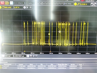
中继:代码不分析此参数。 测量波形后、RMTXD 正常、但 RMRXD 根本没有波形。 至於延误,我会尽快与本公司联络
您能告诉我如何设置 MAC 环回?
请参见下图
您好 Tanmay Patil:
最新的 Rx 波形
rxd0:
rxd1
ethtool -S eth0
root@j7-evm:~# ethtool -S eth0 NIC statistics: p0_rx_good_frames: 331 p0_rx_broadcast_frames: 297 p0_rx_multicast_frames: 34 p0_rx_crc_errors: 0 p0_rx_oversized_frames: 0 p0_rx_undersized_frames: 0 p0_ale_drop: 0 p0_ale_overrun_drop: 0 p0_rx_octets: 23054 p0_tx_good_frames: 0 p0_tx_broadcast_frames: 0 p0_tx_multicast_frames: 0 p0_tx_octets: 0 p0_tx_64B_frames: 299 p0_tx_65_to_127B_frames: 23 p0_tx_128_to_255B_frames: 9 p0_tx_256_to_511B_frames: 0 p0_tx_512_to_1023B_frames: 0 p0_tx_1024B_frames: 0 p0_net_octets: 23054 p0_rx_bottom_fifo_drop: 0 p0_rx_port_mask_drop: 0 p0_rx_top_fifo_drop: 0 p0_ale_rate_limit_drop: 0 p0_ale_vid_ingress_drop: 0 p0_ale_da_eq_sa_drop: 0 p0_ale_block_drop: 0 p0_ale_secure_drop: 0 p0_ale_auth_drop: 0 p0_ale_unknown_ucast: 0 p0_ale_unknown_ucast_bytes: 0 p0_ale_unknown_mcast: 0 p0_ale_unknown_mcast_bytes: 0 p0_ale_unknown_bcast: 0 p0_ale_unknown_bcast_bytes: 0 p0_ale_pol_match: 0 p0_ale_pol_match_red: 0 p0_ale_pol_match_yellow: 0 p0_ale_mcast_sa_drop: 0 p0_ale_dual_vlan_drop: 0 p0_ale_len_err_drop: 0 p0_ale_ip_next_hdr_drop: 0 p0_ale_ipv4_frag_drop: 0 p0_tx_mem_protect_err: 0 p0_tx_pri0: 0 p0_tx_pri1: 0 p0_tx_pri2: 0 p0_tx_pri3: 0 p0_tx_pri4: 0 p0_tx_pri5: 0 p0_tx_pri6: 0 p0_tx_pri7: 0 p0_tx_pri0_bcnt: 0 p0_tx_pri1_bcnt: 0 p0_tx_pri2_bcnt: 0 p0_tx_pri3_bcnt: 0 p0_tx_pri4_bcnt: 0 p0_tx_pri5_bcnt: 0 p0_tx_pri6_bcnt: 0 p0_tx_pri7_bcnt: 0 p0_tx_pri0_drop: 0 p0_tx_pri1_drop: 0 p0_tx_pri2_drop: 0 p0_tx_pri3_drop: 0 p0_tx_pri4_drop: 0 p0_tx_pri5_drop: 0 p0_tx_pri6_drop: 0 p0_tx_pri7_drop: 0 p0_tx_pri0_drop_bcnt: 0 p0_tx_pri1_drop_bcnt: 0 p0_tx_pri2_drop_bcnt: 0 p0_tx_pri3_drop_bcnt: 0 p0_tx_pri4_drop_bcnt: 0 p0_tx_pri5_drop_bcnt: 0 p0_tx_pri6_drop_bcnt: 0 p0_tx_pri7_drop_bcnt: 0 rx_good_frames: 0 rx_broadcast_frames: 0 rx_multicast_frames: 0 rx_pause_frames: 0 rx_crc_errors: 0 rx_align_code_errors: 0 rx_oversized_frames: 0 rx_jabber_frames: 0 rx_undersized_frames: 0 rx_fragments: 0 ale_drop: 0 ale_overrun_drop: 0 rx_octets: 0 tx_good_frames: 331 tx_broadcast_frames: 297 tx_multicast_frames: 34 tx_pause_frames: 0 tx_deferred_frames: 0 tx_collision_frames: 0 tx_single_coll_frames: 0 tx_mult_coll_frames: 0 tx_excessive_collisions: 0 tx_late_collisions: 0 rx_ipg_error: 0 tx_carrier_sense_errors: 0 tx_octets: 23054 tx_64B_frames: 299 tx_65_to_127B_frames: 23 tx_128_to_255B_frames: 9 tx_256_to_511B_frames: 0 tx_512_to_1023B_frames: 0 tx_1024B_frames: 0 net_octets: 23054 rx_bottom_fifo_drop: 0 rx_port_mask_drop: 0 rx_top_fifo_drop: 0 ale_rate_limit_drop: 0 ale_vid_ingress_drop: 0 ale_da_eq_sa_drop: 0 ale_block_drop: 0 ale_secure_drop: 0 ale_auth_drop: 0 ale_unknown_ucast: 0 ale_unknown_ucast_bytes: 0 ale_unknown_mcast: 0 ale_unknown_mcast_bytes: 0 ale_unknown_bcast: 0 ale_unknown_bcast_bytes: 0 ale_pol_match: 0 ale_pol_match_red: 0 ale_pol_match_yellow: 0 ale_mcast_sa_drop: 0 ale_dual_vlan_drop: 0 ale_len_err_drop: 0 ale_ip_next_hdr_drop: 0 ale_ipv4_frag_drop: 0 iet_rx_assembly_err: 0 iet_rx_assembly_ok: 0 iet_rx_smd_err: 355 iet_rx_frag: 0 iet_tx_hold: 0 iet_tx_frag: 0 tx_mem_protect_err: 0 tx_pri0: 331 tx_pri1: 0 tx_pri2: 0 tx_pri3: 0 tx_pri4: 0 tx_pri5: 0 tx_pri6: 0 tx_pri7: 0 tx_pri0_bcnt: 23054 tx_pri1_bcnt: 0 tx_pri2_bcnt: 0 tx_pri3_bcnt: 0 tx_pri4_bcnt: 0 tx_pri5_bcnt: 0 tx_pri6_bcnt: 0 tx_pri7_bcnt: 0 tx_pri0_drop: 0 tx_pri1_drop: 0 tx_pri2_drop: 0 tx_pri3_drop: 0 tx_pri4_drop: 0 tx_pri5_drop: 0 tx_pri6_drop: 0 tx_pri7_drop: 0 tx_pri0_drop_bcnt: 0 tx_pri1_drop_bcnt: 0 tx_pri2_drop_bcnt: 0 tx_pri3_drop_bcnt: 0 tx_pri4_drop_bcnt: 0 tx_pri5_drop_bcnt: 0 tx_pri6_drop_bcnt: 0 tx_pri7_drop_bcnt: 0
您好 Tanmay Patil:
让我提供我们硬件电路设计的原理图。 它看起来非常奇怪。 我们使用 RMII 接口、但 RGMII TD2/3和 RGMII RX2/3都连接到物理芯片1588功能。 请对此进行评估、硬件是否存在重大问题? 如果出现问题、应如何配置 RGMII TD2/3和 RGMII RX2/3的引脚、以使其不受影响。 我们的硬件中间没有连接电阻器、它直接连接到 Mac。 请评价此问题
仍然存在一个巨大的问题、我们的 RMII1_RX ER 未连接、这必须影响 MAC Rx、是否可以通过配置寄存器更改此行为以使 RX 正常工作?
我们发现了问题、连接有问题。这可以关闭、感谢 Tony、感谢 Tanmay Patil。