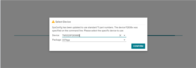
This thread has been locked.
If you have a related question, please click the "Ask a related question" button in the top right corner. The newly created question will be automatically linked to this question.
您好!
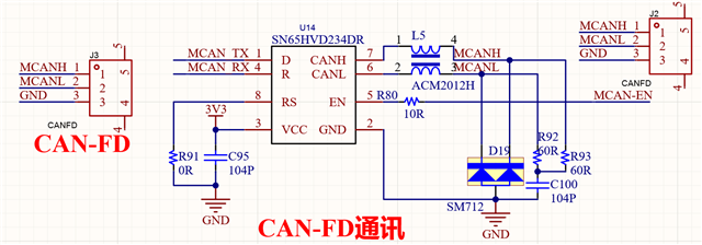
我正在使用TMS320F28388D的CANFD通信代码,我在使用官方提供的代码时发现问题如下:
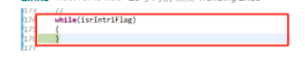
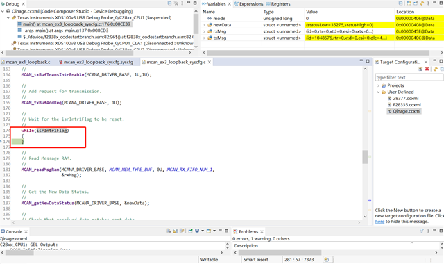
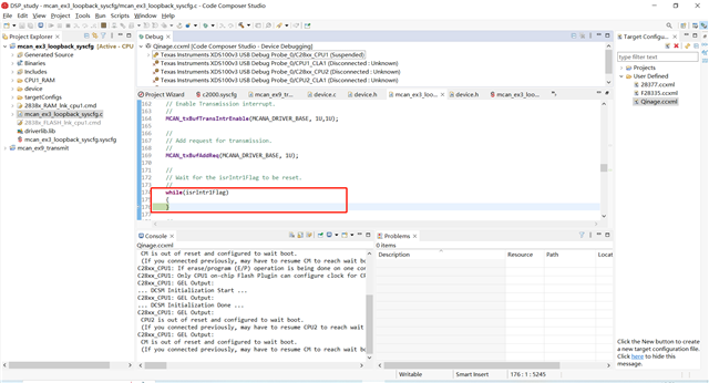
我使用的例程是MCAN_ex3_loopback_syscfg;在下载程序后进行仿真发现代码卡在while循环里面:
具体位置如下:
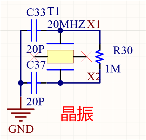
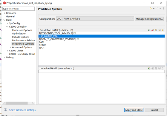
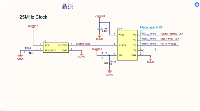
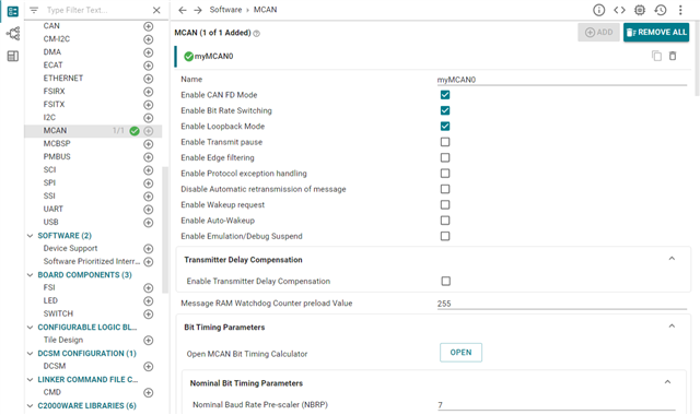
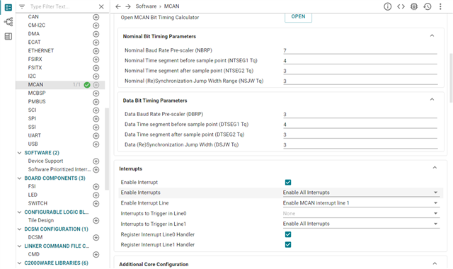
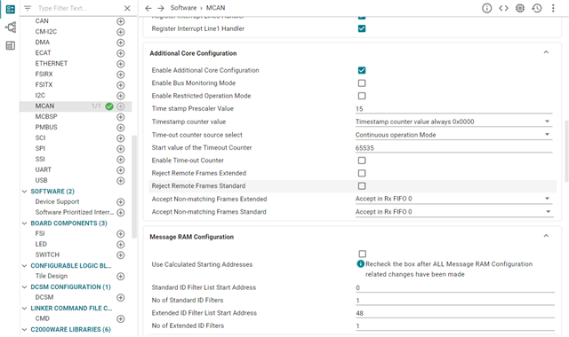
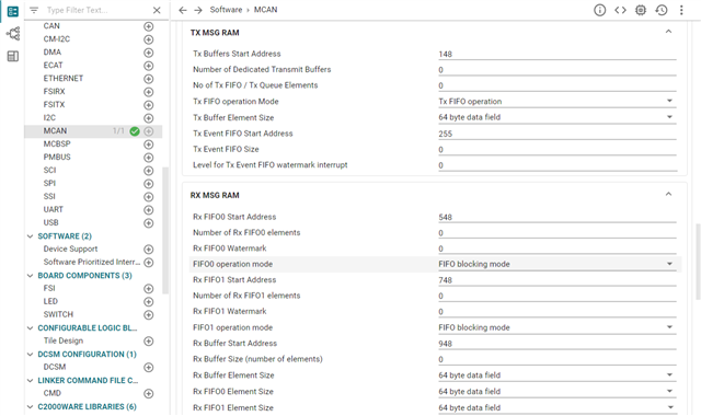
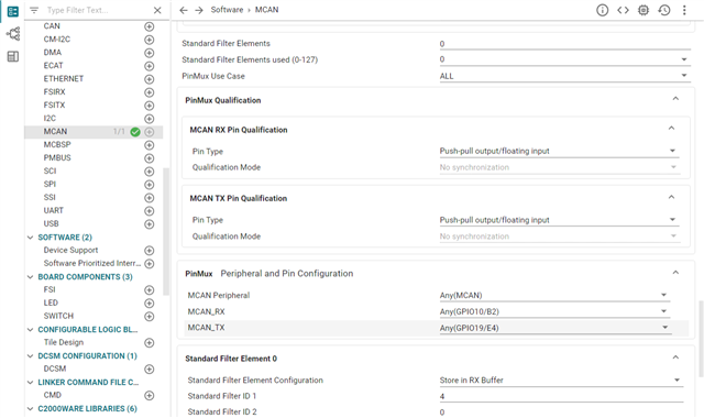
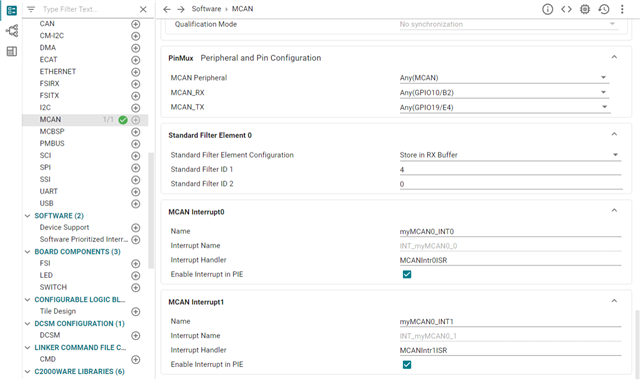
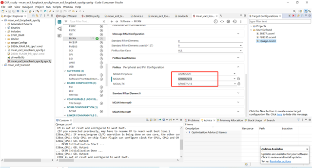
在这个例程中我只修改了我的晶振时钟和引脚,由25MHz变为了20Mhz,引脚由原本的GPIO30,31改为了GPIO36,37,使用了软件配置,具体如下:
请问我该如何解决这个问题,来实现CANFD的通信收发代码?
感谢答复!!
您是否使用TMDSCNCD28388D控制卡?如果是这样,默认时钟是来自带时钟分离器U5的野猪振荡器Y1的25MHz时钟。只是想仔细检查一下,我是否有正确的硬件信息来测试这个例子。
我使用的是GPIO36和GPIO37做CANFD通信引脚,这两个引脚也可以配置为CAN通信,在我使用官方例程配置为CAN通信时能够正常收发信号,我想我的电路应该没有问题,我的CANFD收发电路为:
我使用的芯片最高波特率为1Mbps,但我看官方代码配置为仲裁段为500Kbps,数据段为1Mbps;
使用MCAN_ex1_loopback;例程时发现代码可以运行,不会卡在 while(isrIntr1Flag){}循环里面,但上位机接收到的通信时序不对,还请解答是什么问题?
你好,
内部环回测试不需要外部MCAN引脚或收发器,因此无论配置了哪些引脚,示例环回测试用例都应该运行。以下代码卡住的循环表示MCAN配置不正确:
在振荡器电路上,由于F28388D的内部振荡器具有内置反馈电阻器,因此不需要X1和X2之间的1Meg。还要确保所选的XTAL符合CL和最大ESR的数据表规范。我怀疑该设备没有正确计时,这可能会导致MCAN初始化出现问题。你能监测X1和X2引脚上的时钟活动吗?
您好,上述图片我看不到,我使用示波器检测时钟活动正常,为正常的20Mhz。此外我还做了以下测试:
我使用另外一块开发板做测试,它的晶振电路为:
使用的是官方给定的原理图例程,也发生了同样的问题(一直卡在while(isrIntr1Flag){}),
当我配置我使用的引脚为CAN通信或者将MCAN作为CAN通信时传输是正常的。
所以我怀疑不是晶振的原因。
好的,我使用了我的F28388D控制卡,使用了您在帖子中显示的25MHz时钟源,在运行MCAN示例测试用例时没有看到任何问题。控制卡和软件示例均未进行任何更改。
你能验证你的设置中可能发生了什么变化吗?
您好,整个例程中我没有做过任何修改,唯一的修改就是选则了我使用的芯片
我的主函数代码为:
// // Include Files // #include "driverlib.h" #include "device.h" #include "inc/stw_dataTypes.h" #include "inc/stw_types.h" #include <string.h> #include "board.h" // // Defines // #define MCAN_EXT_ID_AND_MASK (0x1FFFFFFFU) #define MCAN_MSG_INT (0x81200) // // Global Variables. // volatile uint32_t isrIntr0Flag = 1U; volatile uint32_t isrIntr1Flag = 1U; volatile unsigned long msgCount = 0; volatile unsigned long error = 0; // // Function Prototype. // static void MCANFilterConfig(void); static void MCANIntrConfig(void); __interrupt void MCANIntr0ISR(void); __interrupt void MCANIntr1ISR(void); // // Main // void main(void) { volatile uint32_t mode = 0U; MCAN_TxBufElement txMsg; MCAN_RxBufElement rxMsg; MCAN_RxNewDataStatus newData; // // Initialize device clock and peripherals // Device_init(); // // Initialize GPIO and unlock the GPIO configuration registers // Device_initGPIO(); // // Allocate MCAN (a shared peripheral) to CPU1 (C28x) // SysCtl_allocateSharedPeripheral(SYSCTL_PALLOCATE_MCAN_A,0x0U); // // Configure the divisor for the MCAN bit-clock // SysCtl_setMCANClk(SYSCTL_MCANCLK_DIV_5); // // CrossBar and ISR Configuration. // MCANIntrConfig(); // // Board initialization // Board_init(); // // Initialize message to transmit. // txMsg.id = ((uint32_t)(0x4)) << 18U; // Identifier Value. txMsg.rtr = 0U; // Transmit data frame. txMsg.xtd = 0U; // 11-bit standard identifier. txMsg.esi = 0U; // ESI bit in CAN FD format depends only on error // passive flag. txMsg.dlc = 4U; // CAN + CAN FD: transmit frame has 0-8 data bytes. txMsg.brs = 1U; // CAN FD frames transmitted with bit rate // switching. txMsg.fdf = 1U; // Frame transmitted in CAN FD format. txMsg.efc = 1U; // Store Tx events. txMsg.mm = 0xAAU; // Message Marker. // // Data bytes. // txMsg.data[0] = 0x12; txMsg.data[1] = 0x34; txMsg.data[2] = 0x56; txMsg.data[3] = 0x78; // // Write Tx Message to the Message RAM. // MCAN_writeMsgRam(MCANA_DRIVER_BASE, MCAN_MEM_TYPE_BUF, 1U, &txMsg); // // Enable Transmission interrupt. // MCAN_txBufTransIntrEnable(MCANA_DRIVER_BASE, 1U,1U); // // Add request for transmission. // MCAN_txBufAddReq(MCANA_DRIVER_BASE, 1U); // // Wait for the isrIntr1Flag to be reset. // while(isrIntr1Flag) { } // // Read Message RAM. // MCAN_readMsgRam(MCANA_DRIVER_BASE, MCAN_MEM_TYPE_BUF, 0U, MCAN_RX_FIFO_NUM_1, &rxMsg); // // Get the New Data Status. // MCAN_getNewDataStatus(MCANA_DRIVER_BASE, &newData); // // Check that received data matches sent data. // Device will halt here during debug if data doesn't match. // if((txMsg.data[0] != rxMsg.data[0]) || (txMsg.data[1] != rxMsg.data[1]) || (txMsg.data[2] != rxMsg.data[2]) || (txMsg.data[3] != rxMsg.data[3])) { // // Device will halt here if transmitted and received data are // not same. // asm(" ESTOP0"); } else { // // Increment message count if message is received. // msgCount++; } // // Stop Application. // asm(" ESTOP0"); } // // This function will configure X-BAR for MCAN interrupts. // static void MCANIntrConfig(void) { Interrupt_initModule(); Interrupt_initVectorTable(); Interrupt_enableGlobal(); } // // This is Interrupt Service Routine for MCAN interrupt 0. // __interrupt void MCANIntr0ISR(void) { uint32_t intrStatus; intrStatus = MCAN_getIntrStatus(MCANA_DRIVER_BASE); if (MCAN_MSG_INT != intrStatus) { error++; } // // Clear the interrupt Status. // MCAN_clearIntrStatus(MCANA_DRIVER_BASE, intrStatus); // // Update the flag value. // isrIntr0Flag = 0U; // // Acknowledge this interrupt located in group 9 // Interrupt_clearACKGroup(INTERRUPT_ACK_GROUP9); } // // This is Interrupt Service Routine for MCAN interrupt 1. // __interrupt void MCANIntr1ISR(void) { uint32_t intrStatus; intrStatus = MCAN_getIntrStatus(MCANA_DRIVER_BASE); if (MCAN_MSG_INT != intrStatus) { error++; } // // Clearing the interrupt lineNum // HW_WR_FIELD32(MCANA_DRIVER_BASE + MCAN_MCANSS_EOI, MCAN_MCANSS_EOI, 0x2U); // // Clear the interrupt Status. // MCAN_clearIntrStatus(MCANA_DRIVER_BASE, intrStatus); // // Update the flag value. // isrIntr1Flag = 0U; // // Acknowledge this interrupt located in group 9 // Interrupt_clearACKGroup(INTERRUPT_ACK_GROUP9); }
我的sysconfig的配置为:
上述配置为打开之后的默认配置,
代码编译也没有错误,有一个警告说#179-D function "MCANFilterConfig" was declared but never referenced ,删除没有调用的这行代码警告会消失
好吧,看来时钟不是问题。现在,以mcan_ex3_loopback为例,您能否在ISR例程中设置一个断点,如下所示,然后运行以查看代码是否到达中断?
抱歉,我不确定问题是什么,所以我无法发表评论。我以为你有一个设置,可以通过while(IsrIntr1Flag)轮询例程。您能否获取或识别成功运行while轮询例程的设置?我认为我们混淆了这些问题。