This thread has been locked.

If you have a related question, please click the "Ask a related question" button in the top right corner. The newly created question will be automatically linked to this question.

TMS320F28377D: sigma-delta sampling synchronization configuration

Part Number: TMS320F28377D

Hello, experts and colleagues, I would like to ask about the sigma-delta sampling module in chip F28377D.  According to the specification, the condition of PWM11's CMPC synchronizing sdfm module is that one pwm cycle can only generate one CMPC event, what exactly does this event refer to?  What would happen if there were two CMPC events.  Whether the synchronization configuration of the CMPC of PWM11 to the sdfm module is the same as the event triggering configuration in ET, and whether it is affected by the synchronization configuration in ET.

  • Hi huichen,

    We've got this issue and will get back to you soon after I ask the relevant engineer.

  • Thank you very much

  • Hi huichen,

    One PWM cycle can only generate one CMPC event is guaranteed when you're using up count mode or down count mode.

    However when you're using up-down count mode then you are generating two CMPC events. One for when Timebase counter is counting up (1 event) , and another when Timebase counter is counting down (1 event) thus making two events occurring.

    If you wish to use up-down count mode, then make sure to only generate a single event, one event occurring when counting up or one event when counting down. You can verify that the epwm is counting up or down by checking the TBSTS register and bit (CTRDIR). One solution for up-down count is when you have your direction that you do not want the CMPC event to occur, you can change the value of the CMPC within an ISR to a value that will never be true.

    If there are two CMPC events, the filter synchronizer will corrupt SDFM timing. 

    Yes, the CMPC of PWM11 to sdfm module is the same as the event triggering configuration in ET.

  • Engineer Li,

    thank you very much for your answer, but I still have some questions to ask.

    1、Just like you said, when using up count mode or down count mode, one PWM cycle can only generate one CMPC event, but when I use PWM11 down count mode with 10K frequency and configure CMPC equal to 5000, the actual sampling will still have problems. Even without the current, the value of the sample fluctuates.
    2、the CMPC of PWM11 to sdfm module is the same as the event triggering configuration in ET. Can I understand that even if I use the up and down count method, I still only get one event as long as I configure the method of selecting CMPC rising edge trigger in ET?

  • Hi huichen,

    1. Is it possible to share the snippet of code that's failing so our engineer can verify on his end?

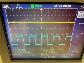
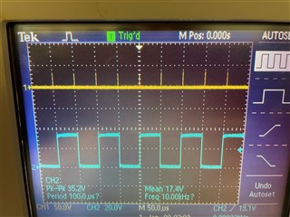
    2. Here are two oscilloscope readings. 

    The first oscilloscope reading is up-down count, and you can see there are two CMPC events occurring for the SYNCOUT pulse. Our engineer have setup PWMA such CMPC = CMPA. When a CMPA event occurs it will toggle high when counting up, and low when counting down. The yellow waveform is the SYNCOUT pulse.

    The second oscilloscope reading Our engineer have setup down-count mode and as you can see only one CMPC event is occurring every pwm period. When CMPA event occurs it will toggle high, and low when TBPRD is zero.

    --

    Thanks & Regards,

    Yale

  • Dear Li,

    I am very glad to receive your answer. I would like to share with you the Settings of my PWM11 and SDFM. As shown below, I configured a switch frequency of 10K, PWM11 in down counting mode, and set CMPC to 5000,It still has fluctuations in the sampling current。

    //

    EPwm11Regs.TBCTL.bit.HSPCLKDIV = TB_DIV1;
    EPwm11Regs.TBCTL.bit.CLKDIV = TB_DIV1;
    EPwm11Regs.TBCTL.bit.PRDLD = TB_IMMEDIATE; // set Immediate load
    EPwm11Regs.TBCTL.bit.CTRMODE = TB_COUNT_DOWN;
    EPwm11Regs.TBPRD = 10000;
    EPwm11Regs.TBCTL.bit.SYNCOSEL = TB_SYNC_IN;
    EPwm11Regs.TBCTL.bit.PHSEN = TB_ENABLE;
    EPwm11Regs.TBPHS.half.TBPHS = EPWM_TBPHS; // Phase is 0
    EPwm11Regs.TBCTL.bit.PHSDIR = TB_UP; 
    EPwm11Regs.TBCTR = 0x0000; // Clear counter


    EPwm11Regs.CMPCTL.bit.SHDWAMODE = CC_SHADOW;
    EPwm11Regs.CMPCTL.bit.SHDWBMODE = CC_SHADOW;
    EPwm11Regs.CMPCTL.bit.LOADAMODE = CC_CTR_ZERO_PRD; // Load on Zero
    EPwm11Regs.CMPCTL.bit.LOADBMODE = CC_CTR_ZERO_PRD;

    EPwm11Regs.CMPA.half.CMPA = DUTYA_INIT; // Set compare A value
    EPwm11Regs.CMPB.half.CMPB = DUTYB_INIT; // Set Compare B value
    EPwm11Regs.CMPC=5000;
    EPwm11Regs.CMPD=5000;

    // Set AQ
    EPwm11Regs.AQCTLA.bit.CAU = AQ_SET; 
    EPwm11Regs.AQCTLA.bit.CAD = AQ_CLEAR; 
    EPwm11Regs.AQCTLB.bit.CBU = AQ_SET; 
    EPwm11Regs.AQCTLB.bit.CBD = AQ_CLEAR; 


    // Set DB
    EPwm11Regs.DBCTL.bit.IN_MODE = DBA_ALL;
    // EPwm11Regs.DBCTL.bit.OUT_MODE = DB_FULL_ENABLE;
    EPwm11Regs.DBCTL.bit.OUT_MODE = DB_DISABLE;
    EPwm11Regs.DBCTL.bit.POLSEL = DB_ACTV_HIC;
    EPwm11Regs.DBRED = EPWM_DBRED_USED;
    EPwm11Regs.DBFED = EPWM_DBFED_USED;

    // Set DC
    EPwm11Regs.DCTRIPSEL.bit.DCAHCOMPSEL = 3; 
    EPwm11Regs.DCACTL.bit.EVT1SRCSEL = DC_EVT1; 
    EPwm11Regs.DCACTL.bit.EVT1FRCSYNCSEL = DC_EVT_ASYNC; 


    // Set TZ
    EPwm11Regs.TZDCSEL.bit.DCAEVT1 = TZ_DCAH_HI; //set TZ tip as DCA HIGH
    EPwm11Regs.TZSEL.bit.DCAEVT1 = 1; // Enable DCAEVT1 as one-shot-trip source for this ePWM module

    EPwm11Regs.TZCTL.bit.TZA = TZ_FORCE_LO; // EPWMxA will go low
    EPwm11Regs.TZCTL.bit.TZB = TZ_FORCE_LO; // EPWMxB will go low

    // Set ET
    EPwm11Regs.ETCNTINITCTL.bit.INTINITEN = 1;
    EPwm11Regs.ETSEL.bit.INTEN = 1;
    EPwm11Regs.ETSEL.bit.INTSEL = 0x4;
    EPwm11Regs.ETSEL.bit.INTSELCMP = 1;
    EPwm11Regs.ETPS.bit.INTPSSEL = 1;
    EPwm11Regs.ETINTPS.bit.INTPRD2 = 1;
    EPwm11Regs.ETFLG.bit.INT = 1;

    //

    Thanks in advance.

    Best regards

    huichen

  • Hi huichen,

    This configuration is just for EPWM. Could you please upload the configuration of SDFM also?

    --

    Thanks & Regards,

    Yale