

Part Number: TMS320F28335
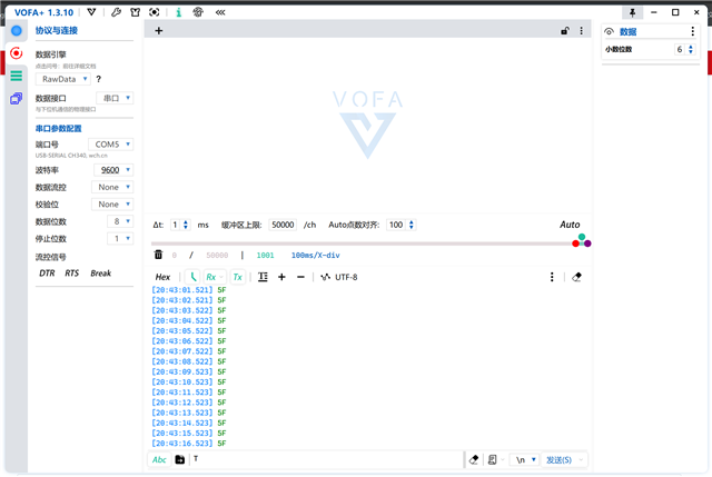
使用f28335的SCIA通过USB-TTL向电脑的串口助手发送数据,结果能够正常接收到数据,但是每个发送的数据都与电脑接收到的数据不一致;
波特率为9600,采用fifo查询方式,配置代码如下:
void InitSciA(Uint32 baud)
{
    Uint16 scibaud = 0;
    unsigned char scihbaud=0;
    unsigned char scilbaud=0;
    scibaud=37500000/(8*baud)-1;
    scihbaud=scibaud>>8;
    scilbaud=scibaud&0xff;

	// Initialize SCI-A:

	//tbd...
    /* Enable internal pull-up for the selected pins */
    // Pull-ups can be enabled or disabled disabled by the user.
    // This will enable the pullups for the specified pins.
    EALLOW;
        GpioCtrlRegs.GPAPUD.bit.GPIO28 = 0;    // Enable pull-up for GPIO28 (SCIRXDA)
        GpioCtrlRegs.GPAPUD.bit.GPIO29 = 0;    // Enable pull-up for GPIO29 (SCITXDA)

    /* Set qualification for selected pins to asynch only */
    // Inputs are synchronized to SYSCLKOUT by default.
    // This will select asynch (no qualification) for the selected pins.

        GpioCtrlRegs.GPAQSEL2.bit.GPIO28 = 3;  // Asynch input GPIO28 (SCIRXDA)

    /* Configure SCI-A pins using GPIO regs*/
    // This specifies which of the possible GPIO pins will be SCI functional pins.

        GpioCtrlRegs.GPAMUX2.bit.GPIO28 = 1;   // Configure GPIO28 for SCIRXDA operation
        GpioCtrlRegs.GPAMUX2.bit.GPIO29 = 1;   // Configure GPIO29 for SCITXDA operation

    EDIS;

    SciaRegs.SCIFFTX.all=0xE040;
    SciaRegs.SCIFFRX.all=0x204f;
    SciaRegs.SCIFFCT.all=0x0;
    SciaRegs.SCICCR.all =0x0007;
    SciaRegs.SCICTL1.all =0x0003;
    SciaRegs.SCICTL2.all =0x0003;
    SciaRegs.SCICTL2.bit.TXINTENA =1;
    SciaRegs.SCICTL2.bit.RXBKINTENA =1;
    SciaRegs.SCIHBAUD =scihbaud; // 9600 baud @LSPCLK = 37.5MHz.
    SciaRegs.SCILBAUD =scilbaud;
    SciaRegs.SCICCR.bit.LOOPBKENA = 1; // Enable loop back
    SciaRegs.SCICTL1.all =0x0023; // Relinquish SCI from Reset
    }

    //scia发送单个字节
void SCIA_sendbyte(int byte)
{
    while(SciaRegs.SCIFFTX.bit.TXFFST != 0)
    {

    }
    SciaRegs.SCITXBUF = byte;
//    while(SciaRegs.SCICTL2.bit.TXRDY != 1)
//        {
//
//        }
//        SciaRegs.SCITXBUF = byte;
}

//sci发送字符串
void SCIA_sendstring(char *msg)
{
    int i=0;

    while(msg[i] != '\0')
    {
        SCIA_sendbyte(msg[i]);
        i++;
    }
}

//sci接收单个字节
Uint16 SCIA_recievebyte(void)
{
    Uint16 byte;
    while(SciaRegs.SCIFFRX.bit.RXFFST !=1)
    {

    }
    byte = SciaRegs.SCIRXBUF.all;
    return byte;
}
然后在100ms的定时中断里面发送数据
interrupt void  TINT0_ISR(void)      // CPU-Timer 0
{
//    char *msg;
  // Insert ISR Code here

  // To receive more interrupts from this PIE group, acknowledge this interrupt
  // PieCtrlRegs.PIEACK.all = PIEACK_GROUP1;

  // Next two lines for debug only to halt the processor here
  // Remove after inserting ISR Code
//  asm ("      ESTOP0");
//  for(;;);

    if(CpuTimer0.InterruptCount == 0){
        CpuTimer0.InterruptCount++;
        LED1 = 1;
    }
    else{
        CpuTimer0.InterruptCount--;
        LED1 = 0;
    }
    temp1 = TMP100_Read();
//    msg = "Hello World!\r\n";
//    Fot(temp1, 0, 0);
//    SCIA_sendstring(msg);


    SCIA_sendbyte(0x41);
    CpuTimer0Regs.TCR.bit.TIF = 1; //清定时器中断标志位
    PieCtrlRegs.PIEACK.bit.ACK1 = 1; //可响应同组其他中断
    EINT; //开全局中断
}
发送的明明是0x41,接收到的却是0x5F,换了其他串口助手软件也是这样
通过仿真器调试,寄存器里的数据都正确
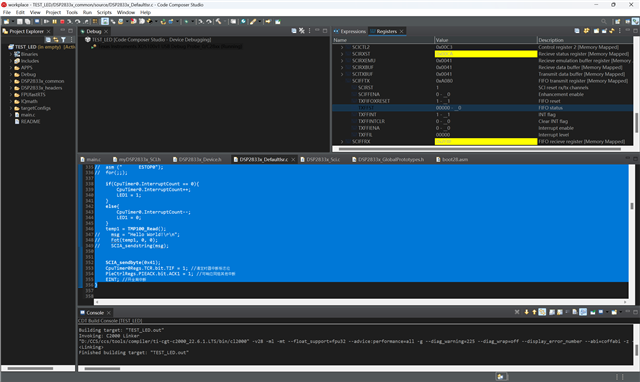
请教各位大佬,到底是什么原因呢?

