This thread has been locked.
If you have a related question, please click the "Ask a related question" button in the top right corner. The newly created question will be automatically linked to this question.
各位先進好
F5419A 有4個UART PORT.
使用XT2 (8MHZ) 做為CLOCK SOURCE.
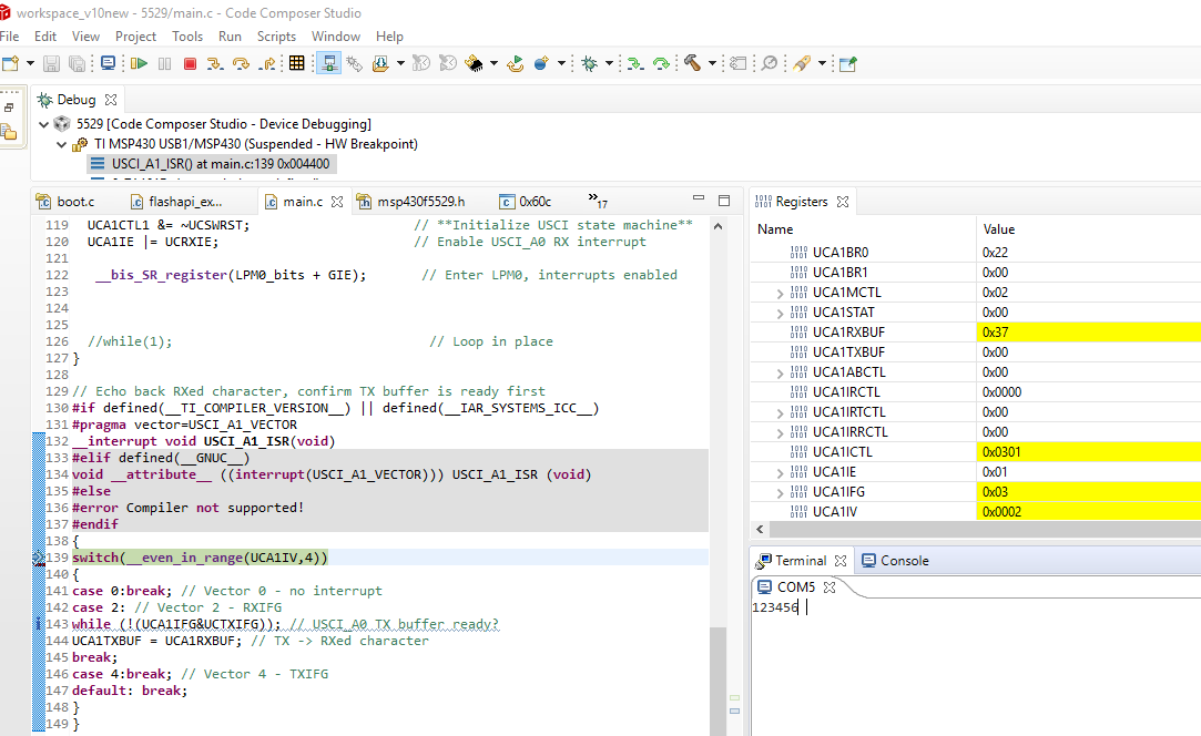
單獨使用 UART0.UART2,UART3通訊115200bps 都正常
一旦啟用UART1, 全部UART失效.
且 P11.2 輸出從8MHZ 變1MHZ?
請問 先進 是否有建議 ??000_UART1_FAIL_XT2.pdf
//****************************************************************************** // MSP430F543xA Demo - USCI_A0, 115200 UART Echo ISR, DCO SMCLK // // Description: Echo a received character, RX ISR used. Normal mode is LPM0. // USCI_A0 RX interrupt triggers TX Echo. // Baud rate divider with 1048576hz = 1048576/115200 = ~9.1 (009h|01h) // ACLK = REFO = ~32768Hz, MCLK = SMCLK = default DCO = 32 x ACLK = 1048576Hz // See User Guide for baud rate divider table // // MSP430F5438A // ----------------- // /|\| | // | | | // --|RST | // | | // | P3.4/UCA0TXD|------------> // | | 115200 - 8N1 // | P3.5/UCA0RXD|<------------ // // M. Morales // Texas Instruments Inc. // June 2009 // Built with CCE Version: 3.2.2 and IAR Embedded Workbench Version: 4.11B //****************************************************************************** // UART0~UART3 �P�ɱҰ� . �̧ǭӧO��X ���\ #include <msp430.h> #define PUMP P1OUT ^= 0x01 //BUZ �w��DOG unsigned int KI; void SetVcoreUp (unsigned int level); int main(void) { WDTCTL = WDTPW + WDTHOLD; // Stop WDT P11DIR |= 0x07; // ACLK, MCLK, SMCLK set out to pins P11SEL |= 0x07; // P11.0,1,2=8MHZ //===========================STEP 2 =============================== SetVcoreUp(PMMCOREV_1); SetVcoreUp(PMMCOREV_2); // Set VCore to 1.8MHz for 20MHz P5SEL |= 0x0C; // ###### Port select XT2 UCSCTL6 &= ~XT2OFF; // ###### Enable XT2 ################# UCSCTL3 |= SELREF_2; // FLLref = REFO Since LFXT1 is not used, // sourcing FLL with LFXT1 can cause XT1OFFG flag to set UCSCTL4 |= SELA_2; // ACLK=REFO,SMCLK=DCO,MCLK=DCO // Loop until XT1,XT2 & DCO stabilizes do { UCSCTL7 &= ~(XT2OFFG + XT1LFOFFG + XT1HFOFFG + DCOFFG); // Clear XT2,XT1,DCO fault flags SFRIFG1 &= ~OFIFG; // Clear fault flags }while (SFRIFG1&OFIFG); // Test oscillator fault flag //UCSCTL6 &= ~XT2DRIVE0; // Decrease XT2 Drive according to PUMP; // expected frequency //�ʥH�U�T�� �L�k����........... for(KI=0;KI<50000;KI++){ //�]��í�w�ɶ�����. �ɭPSMCLK �������� PUMP; PUMP; //�ҥH�W�[��LOOP. �Y�i�bXT2 í�w��.�~�ií�w����SMCLK=MCLK=XT2 } // %%% ���B�i�H�M�w SMCLK�PMCLK �W�v=10MHZ �� 1MHZ %%% //UCSCTL4 |= SELS_5 + SELM_5; // SMCLK=XT2=8MHZ MCLK=10MHZ �i�H�ߧY����P1.1 ��X�g��=1.6us UCSCTL4 |= SELS_5; // SMCLK=XT2=8MHZ MCLK=1MHZ �i�H�ߧY����P1.1 ��X�g��=16us PUMP; for(KI=0;KI<50000;KI++){ //�]��í�w�ɶ�����. �ɭPSMCLK �������� PUMP; PUMP; //�ҥH�W�[��LOOP. �Y�i�bXT2 í�w��.�~�ií�w����SMCLK=MCLK=XT2 } // P3SEL = 0x30; // P3.4,5 = USCI_A0 TXD/RXD UCA0CTL1 |= UCSWRST; // **Put state machine in reset** UCA0CTL1 |= UCSSEL_2; // SMCLK UCA0BR0 = 69; // 1MHz 115200 (see User's Guide) UCA0BR1 = 0; // 1MHz 115200 UCA0MCTL |= UCBRS_1 + UCBRF_0; // Modulation UCBRSx=1, UCBRFx=0 UCA0CTL1 &= ~UCSWRST; // **Initialize USCI state machine** /* // P5SEL = 0xC0; // P5 = USCI_A1 TXD/RXD UCA1CTL1 |= UCSWRST; // **Put state machine in reset** UCA1CTL1 |= UCSSEL_2; // SMCLK UCA1BR0 = 69; // 1MHz 115200 (see User's Guide) UCA1BR1 = 0; // 1MHz 115200 UCA1MCTL |= UCBRS_1 + UCBRF_0; // Modulation UCBRSx=1, UCBRFx=0 UCA1CTL1 &= ~UCSWRST; // **Initialize USCI state machine** */ // P9SEL = 0x30; // P9 = USCI_A2 TXD/RXD UCA2CTL1 |= UCSWRST; // **Put state machine in reset** UCA2CTL1 |= UCSSEL_2; // SMCLK UCA2BR0 = 69; // 1MHz 115200 (see User's Guide) UCA2BR1 = 0; // 1MHz 115200 UCA2MCTL |= UCBRS_1 + UCBRF_0; // Modulation UCBRSx=1, UCBRFx=0 UCA2CTL1 &= ~UCSWRST; // **Initialize USCI state machine** // P10SEL = 0x30; // P10 = USCI_A3 TXD/RXD UCA3CTL1 |= UCSWRST; // **Put state machine in reset** UCA3CTL1 |= UCSSEL_2; // SMCLK UCA3BR0 = 69; // 1MHz 115200 (see User's Guide) UCA3BR1 = 0; // 1MHz 115200 UCA3MCTL |= UCBRS_1 + UCBRF_0; // Modulation UCBRSx=1, UCBRFx=0 UCA3CTL1 &= ~UCSWRST; // **Initialize USCI state machine** while(1){ while(!(UCA0IFG & UCTXIFG)); //���� UART ��X�\�� UCA0TXBUF=0x41; //���� UART ��X�\�� while(!(UCA1IFG & UCTXIFG)); //���� UART ��X�\�� UCA1TXBUF=0x42; //���� UART ��X�\�� while(!(UCA2IFG & UCTXIFG)); //���� UART ��X�\�� UCA2TXBUF=0x43; //���� UART ��X�\�� while(!(UCA3IFG & UCTXIFG)); //���� UART ��X�\�� UCA3TXBUF=0x44; //���� UART ��X�\�� __delay_cycles(1000000); //���� UART ��X�\�� } } void SetVcoreUp (unsigned int level) { // Open PMM registers for write PMMCTL0_H = PMMPW_H; // Set SVS/SVM high side new level SVSMHCTL = SVSHE + SVSHRVL0 * level + SVMHE + SVSMHRRL0 * level; // Set SVM low side to new level SVSMLCTL = SVSLE + SVMLE + SVSMLRRL0 * level; // Wait till SVM is settled while ((PMMIFG & SVSMLDLYIFG) == 0); // Clear already set flags PMMIFG &= ~(SVMLVLRIFG + SVMLIFG); // Set VCore to new level PMMCTL0_L = PMMCOREV0 * level; // Wait till new level reached if ((PMMIFG & SVMLIFG)) while ((PMMIFG & SVMLVLRIFG) == 0); // Set SVS/SVM low side to new level SVSMLCTL = SVSLE + SVSLRVL0 * level + SVMLE + SVSMLRRL0 * level; // Lock PMM registers for write access PMMCTL0_H = 0x00; }
很抱歉,我找了一下这边的板子都是没有XT2的,所以无法测试您的程序
但是我看了您的代码,并没有发现问题
tojijn Twu 说:一旦啟用UART1, 全部UART失效.
且 P11.2 輸出從8MHZ 變1MHZ?
请问您在单独测试UART1的时候,程序是会卡在哪里?UART寄存器哪里异常?
>一旦啟用UART1 .則SMCLK 從8MHZ 變成原本之1MHZ.. 就這樣.
>所以我的對策是
UART 全部使用內建DCO=1.034MHZ. 115200bps. 四個channel 都OK可用
>如果想要更精準ˋ之CRYSTAL XT2. 則必須捨棄 UART1
以上是 問題與解法 謝謝
请问您现在情况怎么样了?
我在MSP430F5529 LAUNCHPAD上测试了一下,使用XT2 4Mhz/UART1是可以正常使用的
代码如下
/* --COPYRIGHT--,BSD_EX * Copyright (c) 2012, Texas Instruments Incorporated * All rights reserved. * * Redistribution and use in source and binary forms, with or without * modification, are permitted provided that the following conditions * are met: * * * Redistributions of source code must retain the above copyright * notice, this list of conditions and the following disclaimer. * * * Redistributions in binary form must reproduce the above copyright * notice, this list of conditions and the following disclaimer in the * documentation and/or other materials provided with the distribution. * * * Neither the name of Texas Instruments Incorporated nor the names of * its contributors may be used to endorse or promote products derived * from this software without specific prior written permission. * * THIS SOFTWARE IS PROVIDED BY THE COPYRIGHT HOLDERS AND CONTRIBUTORS "AS IS" * AND ANY EXPRESS OR IMPLIED WARRANTIES, INCLUDING, BUT NOT LIMITED TO, * THE IMPLIED WARRANTIES OF MERCHANTABILITY AND FITNESS FOR A PARTICULAR * PURPOSE ARE DISCLAIMED. IN NO EVENT SHALL THE COPYRIGHT OWNER OR * CONTRIBUTORS BE LIABLE FOR ANY DIRECT, INDIRECT, INCIDENTAL, SPECIAL, * EXEMPLARY, OR CONSEQUENTIAL DAMAGES (INCLUDING, BUT NOT LIMITED TO, * PROCUREMENT OF SUBSTITUTE GOODS OR SERVICES; LOSS OF USE, DATA, OR PROFITS; * OR BUSINESS INTERRUPTION) HOWEVER CAUSED AND ON ANY THEORY OF LIABILITY, * WHETHER IN CONTRACT, STRICT LIABILITY, OR TORT (INCLUDING NEGLIGENCE OR * OTHERWISE) ARISING IN ANY WAY OUT OF THE USE OF THIS SOFTWARE, * EVEN IF ADVISED OF THE POSSIBILITY OF SUCH DAMAGE. * ******************************************************************************* * * MSP430 CODE EXAMPLE DISCLAIMER * * MSP430 code examples are self-contained low-level programs that typically * demonstrate a single peripheral function or device feature in a highly * concise manner. For this the code may rely on the device's power-on default * register values and settings such as the clock configuration and care must * be taken when combining code from several examples to avoid potential side * effects. Also see www.ti.com/grace for a GUI- and www.ti.com/msp430ware * for an API functional library-approach to peripheral configuration. * * --/COPYRIGHT--*/ //****************************************************************************** // MSP430F552x Demo - XT2 sources MCLK & SMCLK // // Description: This program demonstrates using XT2 to source MCLK. XT1 is not // connected in this case. // // By default, LFXT1 is requested by the following modules: // - FLL // - ACLK // If LFXT1 is NOT used and if the user does not change the source modules, // it causes the XT1xxOFIFG flag to be set because it is constantly looking // for LFXT1. OFIFG, global oscillator fault flag, will always be set if LFXT1 // is set. Hence, it is important to ensure LFXT1 is no longer being sourced // if LFXT1 is NOT used. // MCLK = XT2 // // MSP430F552x // ----------------- // /|\ | | // | | | // ---|RST | // | XT2IN|- // | | HF XTAL (455kHz - 16MHz) // | XT2OUT|- // | | // | P7.7|--> MCLK = XT2 // | P2.2|--> SMCLK = XT2 // // Bhargavi Nisarga // Texas Instruments Inc. // April 2009 // Built with CCSv4 and IAR Embedded Workbench Version: 4.21 //****************************************************************************** #include <msp430.h> int main(void) { WDTCTL = WDTPW + WDTHOLD; // Stop watchdog timer P2DIR |= BIT2; // SMCLK set out to pins P2SEL |= BIT2; P7DIR |= BIT7; // MCLK set out to pins P7SEL |= BIT7; P5SEL |= BIT2+BIT3; // Port select XT2 UCSCTL6 &= ~XT2OFF; // Enable XT2 UCSCTL3 |= SELREF_2; // FLLref = REFO // Since LFXT1 is not used, // sourcing FLL with LFXT1 can cause // XT1OFFG flag to set UCSCTL4 |= SELA_2; // ACLK=REFO,SMCLK=DCO,MCLK=DCO // Loop until XT1,XT2 & DCO stabilizes - in this case loop until XT2 settles do { UCSCTL7 &= ~(XT2OFFG + XT1LFOFFG + DCOFFG); // Clear XT2,XT1,DCO fault flags SFRIFG1 &= ~OFIFG; // Clear fault flags }while (SFRIFG1&OFIFG); // Test oscillator fault flag UCSCTL6 &= ~XT2DRIVE0; // Decrease XT2 Drive according to // expected frequency UCSCTL4 |= SELS_5 + SELM_5; // SMCLK=MCLK=XT2 //UART P4SEL |= BIT4+BIT5; // P4.5 = RXD, P4.4=TXD UCA1CTL1 |= UCSWRST; // **Put state machine in reset** UCA1CTL1 |= UCSSEL_2; // SMCLK UCA1BR0 = 34; // 4MHz 115200 (see User's Guide) UCA1BR1 = 0; // 4MHz 115200 UCA1MCTL |= UCBRS_1 + UCBRF_0; // Modulation UCBRSx=1, UCBRFx=0 UCA1CTL1 &= ~UCSWRST; // **Initialize USCI state machine** UCA1IE |= UCRXIE; // Enable USCI_A0 RX interrupt __bis_SR_register(LPM0_bits + GIE); // Enter LPM0, interrupts enabled //while(1); // Loop in place } // Echo back RXed character, confirm TX buffer is ready first #if defined(__TI_COMPILER_VERSION__) || defined(__IAR_SYSTEMS_ICC__) #pragma vector=USCI_A1_VECTOR __interrupt void USCI_A1_ISR(void) #elif defined(__GNUC__) void __attribute__ ((interrupt(USCI_A1_VECTOR))) USCI_A1_ISR (void) #else #error Compiler not supported! #endif { switch(__even_in_range(UCA1IV,4)) { case 0:break; // Vector 0 - no interrupt case 2: // Vector 2 - RXIFG while (!(UCA1IFG&UCTXIFG)); // USCI_A0 TX buffer ready? UCA1TXBUF = UCA1RXBUF; // TX -> RXed character break; case 4:break; // Vector 4 - TXIFG default: break; } }